
DIY: vehicle speed sensor cleaning/replacement
I recently took apart the entire interior for some deep cleaning and upon full reassemble, I wanted to take my Solara out for a spin. Less than a mile from my house, the speedometer dips suddenly and (BAM!!!) check engine light comes on. Frustrated, I pulled over, popped off the positive battery lead and waited for a few minutes. Reconnected to the battery term and started her up…check engine light gone. Put it in drive and drove a few miles, no problems. Take a fast left turn and the transmission down shifts into first (like I was goosing it), then pops up into second, then quickly into third all while the speedometer dips and jumps for a few seconds.
Took it to Advance Auto Parts for a OBD code read. Got a P0500 - Vehicle Speed Sensor Malfunction. Part # 090-5018 for new sensor from AAP, and more than $150 bucks.
I did have AAP worker clear the CEL. It drove fine around town (taking it easy), but I hit the country roads and tried to reproduce the problem. At cruising speed (40 mph), I could punch it, have it kick down and then, party over, CEL on, speedometer going crazy, and aberrant shifting. Also a little higher idle at a stop. Even on slow takeoff from a stop, the engine would wind out to 3krpm from first to second and second to third, but bog down and shift too early into the high gears. Cool side note though…at cruising speeds, the speedometer would drop to 0 and the odometer would not roll fwd either (trips or total miles). I realized this is not a problem, but a gift that keeps on giving.
Problem was consistent with what I read on TN and other sites (http://www.obd-codes.com/p0500). Was not able to find a DIY for repair/replace, so here’s my rendition. I’m no mechanic, but a cheapskate with a camera.
This DIY is shown for a 2000 Solara SLE (V6 3.0L, auto, 70k miles). I am new to Toyota, so I don’t know what other models this would apply to. I appreciate Eye8Pussies compilation of DIYs. I hope this DIY makes the list.
Tools needed: ratchet wrench w/ extension, 10 mm socket, Phillips screwdriver, light (if needed), thin arm or long fingers (your choice).
The process:
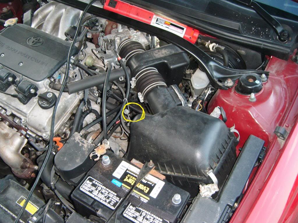
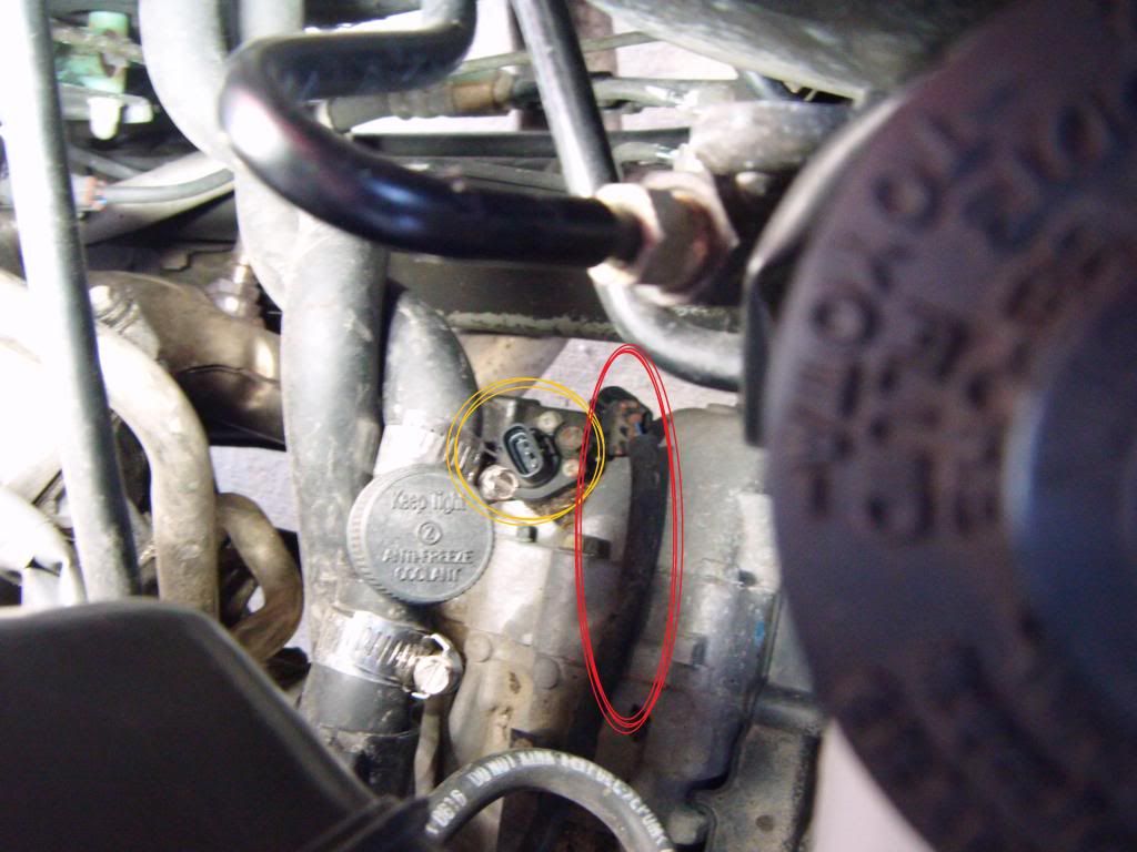
The yellow oval indicates approximate location of the sensor. The sensor is actually located on top of the transmission, close to the firewall (note the thin arm or long finger requirement). I have read that a lot of people have had a hard time finding it, so I posted several pictures.
![Image]()
Off to the driver’s side of the vehicle, you can actually see the sensor under a bunch of hoses, wires, etc. I go ahead and pop off the leads to the battery. Two reasons, first it will clear the CEL and second, I’ve been shocked a few times just messing around and I have heard of some bad stories about screwing up the ECM if accidently short a circuit.
![Image]()
Yellow arrow shows the sensor and red arrow shows the cable connected to it.
![Image]()
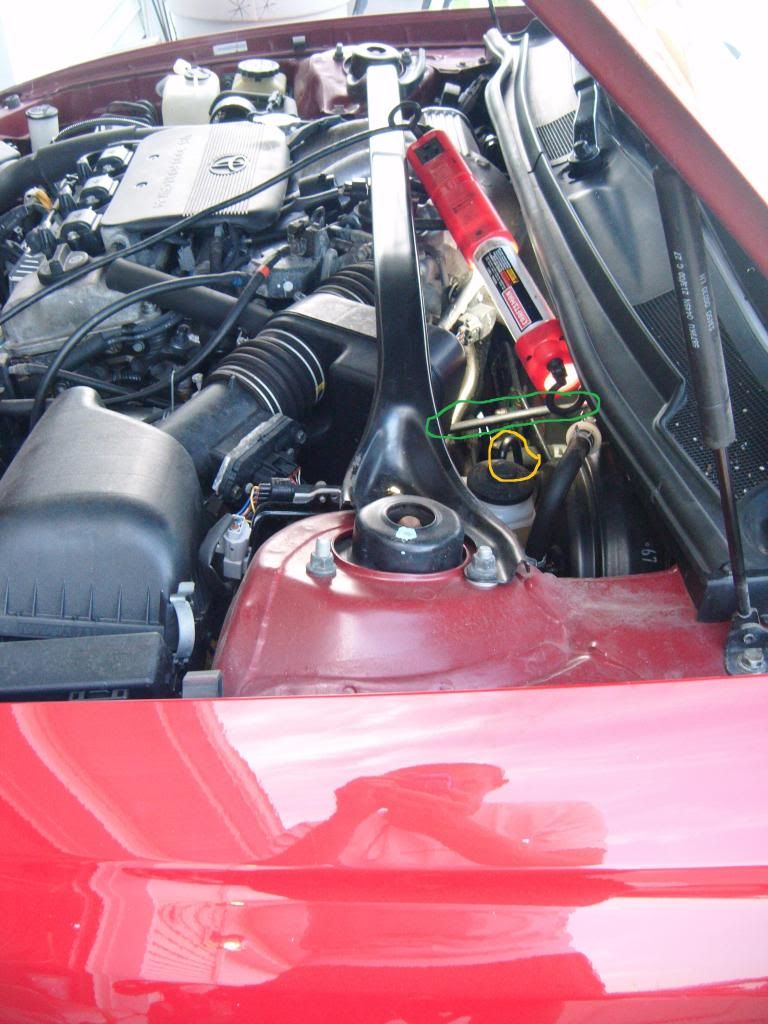
Shown is far drivers side view. Outlined in green is flexible hose you can move during this work. Outlined in orange are the rigid brake lines that you shouldn’t bend, break, or mess with.
![Image]()
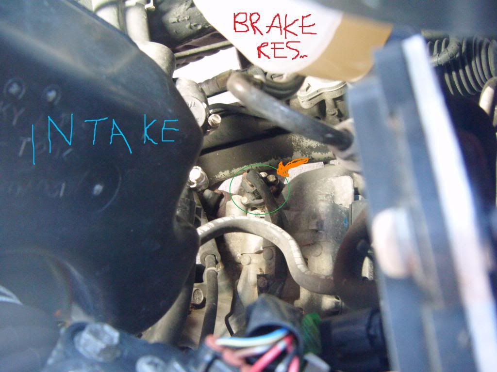
Up close pic of between the junk you got to work around. Green is sensor. Orange arrow indicates the single 10 mm bolt that must be removed to take out the sensor from the transmission case.
![Image]()
Remove the sensor wire by disconnecting. I basically just squeezed around the base of the connection and pulled straight up. Orange = sensor, red = disconnected wire. If you cannot disconnect the sensor wire, you could use an open end 10 mm wrench and remove the bolt and then the sensor, and finally disconnect the wire. You can see in the next picture the small catch at the connector union that holds the sensor and sensor wire together.
![Image]()
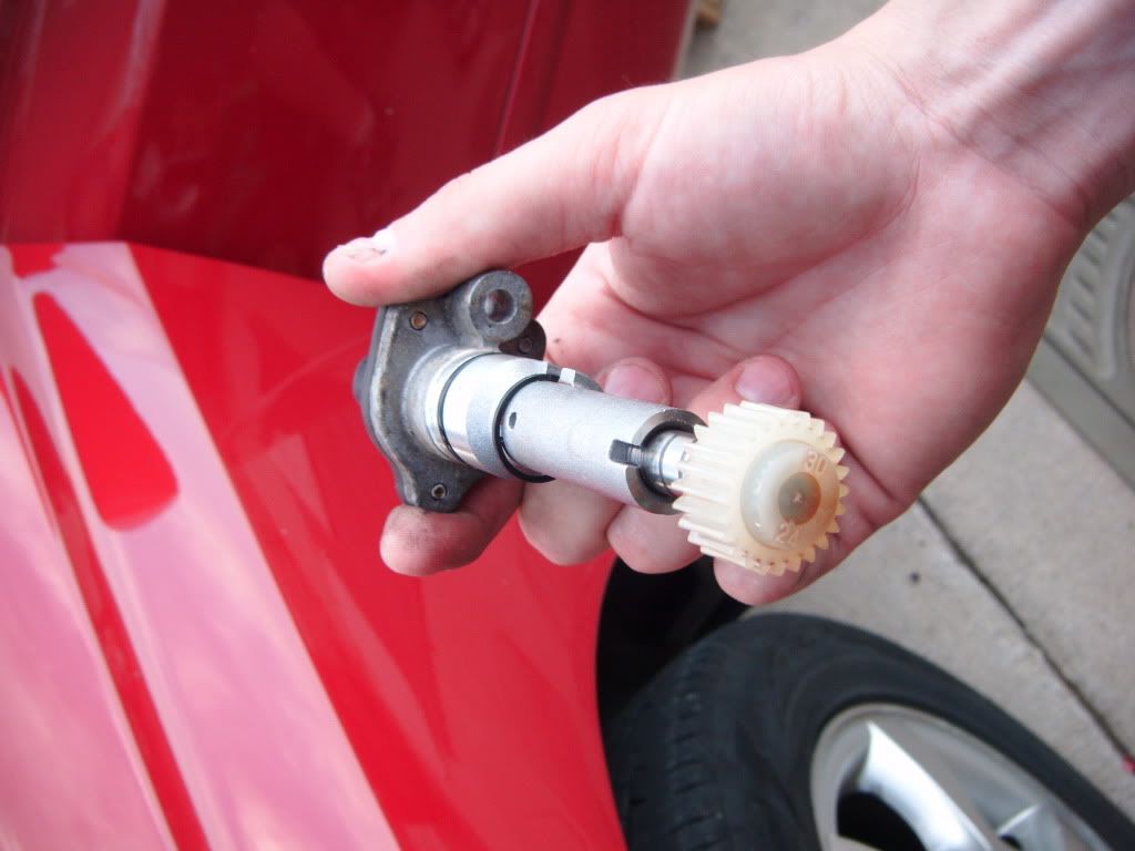
I removed the bolt with my socket and ratchet wrench and carefully pulled the sensor straight out.
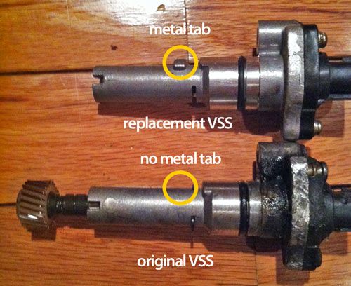
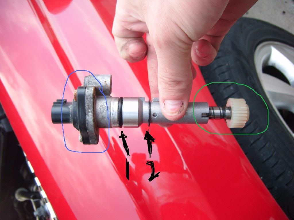
Shown is the sensor. Blue is top of the sensor where the mechanical motion is “sensed” by the electrical leads within the unit. Black arrows show the (1) rubber O-ring (replace if damaged) and (2) retaining ring that ensures the rotatable rod makes tight interaction with the internal electrical leads. Green is the gear that, well…moves. KEEP this gear, rotating rod, and metal retaining ring (2) if you purchase a new sensor from a store. My guess is that the new sensor unit will not include these parts.
![Image]()
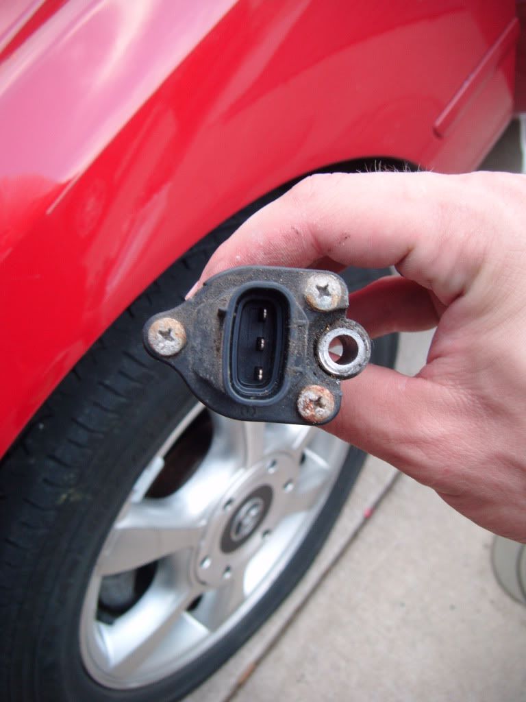
Top view of the sensor where wire leads connect. Clean if needed.
![Image]()
Bottom view.
![Image]()
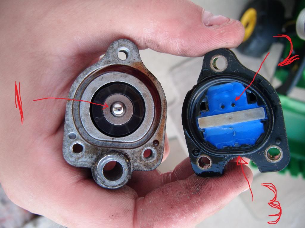
I removed the three screws using a Phillips screwdriver to clean the interior components. Be very careful when removing these screws because black plastic top of the sensor has a bit of a spring-like tension hold to the metal sensor housing. Be sure to not lose the bearing shown (1). This magic BB probably controls the entire ECM J. Clean the sensor contacts (2) and rubber O-ring. Replace ring if needed, though this may be pre-formed and a pain to “fit” with a standard O-ring replacement.
![Image]()
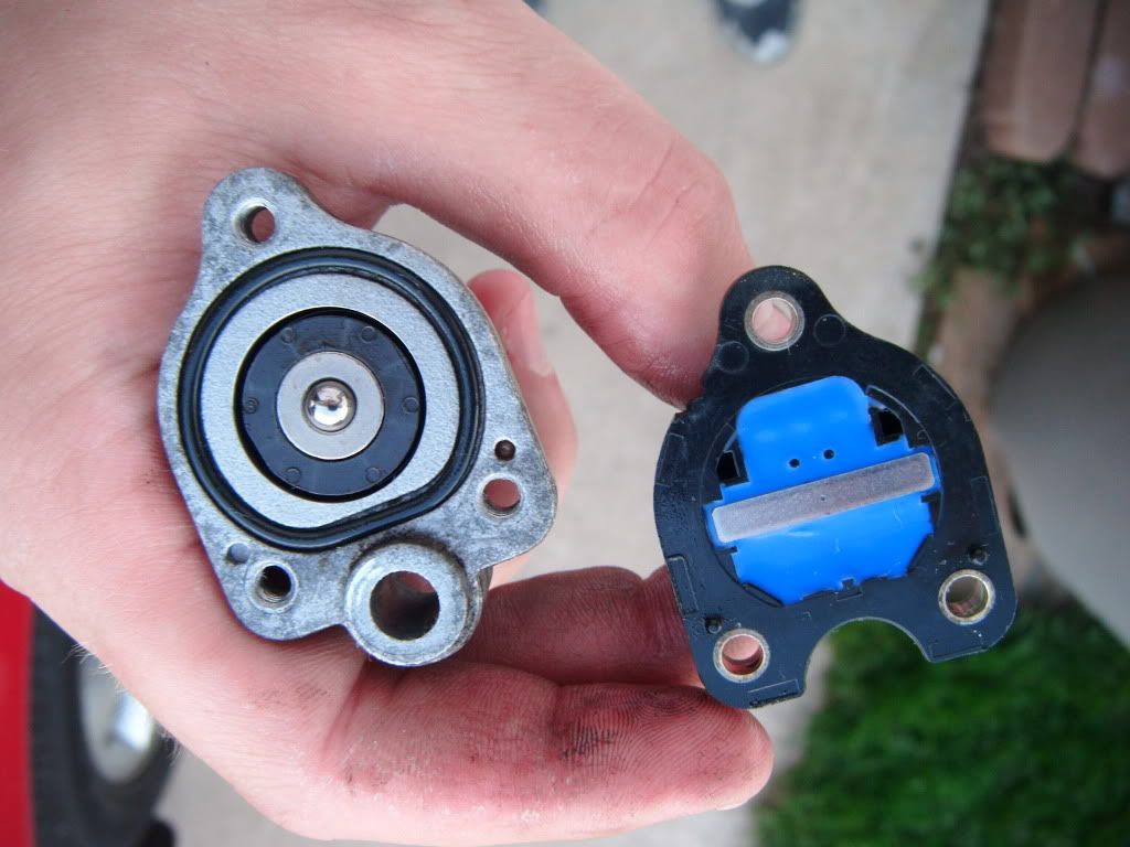
Shown are the cleaned components.
![Image]()
To finish up I joined the top (plastic) component with the bottom (metal) component and tightened the three screws snug. No need to gorilla torque, remember this is plastic on metal! Just be sure to tighten evenly. Next, carefully replace the sensor unit into the opening on the transmission. You may have to jiggle it a bit to get the gear wheel to align with the other gear residing in the transmission itself. Hand thread the bolt, then tighten down with wrench. Next, slide the wire harness back onto the sensor and “feel” the click. Finally, connect the battery terminals if you took them off. Now get behind the wheel and start it up. Drive around and enjoy!
I have not had any problems whatsoever. No CEL or speedo/tach/odometer problems, even while driving it hard!
I recently took apart the entire interior for some deep cleaning and upon full reassemble, I wanted to take my Solara out for a spin. Less than a mile from my house, the speedometer dips suddenly and (BAM!!!) check engine light comes on. Frustrated, I pulled over, popped off the positive battery lead and waited for a few minutes. Reconnected to the battery term and started her up…check engine light gone. Put it in drive and drove a few miles, no problems. Take a fast left turn and the transmission down shifts into first (like I was goosing it), then pops up into second, then quickly into third all while the speedometer dips and jumps for a few seconds.
Took it to Advance Auto Parts for a OBD code read. Got a P0500 - Vehicle Speed Sensor Malfunction. Part # 090-5018 for new sensor from AAP, and more than $150 bucks.
I did have AAP worker clear the CEL. It drove fine around town (taking it easy), but I hit the country roads and tried to reproduce the problem. At cruising speed (40 mph), I could punch it, have it kick down and then, party over, CEL on, speedometer going crazy, and aberrant shifting. Also a little higher idle at a stop. Even on slow takeoff from a stop, the engine would wind out to 3krpm from first to second and second to third, but bog down and shift too early into the high gears. Cool side note though…at cruising speeds, the speedometer would drop to 0 and the odometer would not roll fwd either (trips or total miles). I realized this is not a problem, but a gift that keeps on giving.
Problem was consistent with what I read on TN and other sites (http://www.obd-codes.com/p0500). Was not able to find a DIY for repair/replace, so here’s my rendition. I’m no mechanic, but a cheapskate with a camera.
This DIY is shown for a 2000 Solara SLE (V6 3.0L, auto, 70k miles). I am new to Toyota, so I don’t know what other models this would apply to. I appreciate Eye8Pussies compilation of DIYs. I hope this DIY makes the list.
Tools needed: ratchet wrench w/ extension, 10 mm socket, Phillips screwdriver, light (if needed), thin arm or long fingers (your choice).
The process:
The yellow oval indicates approximate location of the sensor. The sensor is actually located on top of the transmission, close to the firewall (note the thin arm or long finger requirement). I have read that a lot of people have had a hard time finding it, so I posted several pictures.

Off to the driver’s side of the vehicle, you can actually see the sensor under a bunch of hoses, wires, etc. I go ahead and pop off the leads to the battery. Two reasons, first it will clear the CEL and second, I’ve been shocked a few times just messing around and I have heard of some bad stories about screwing up the ECM if accidently short a circuit.
Yellow arrow shows the sensor and red arrow shows the cable connected to it.

Shown is far drivers side view. Outlined in green is flexible hose you can move during this work. Outlined in orange are the rigid brake lines that you shouldn’t bend, break, or mess with.
Up close pic of between the junk you got to work around. Green is sensor. Orange arrow indicates the single 10 mm bolt that must be removed to take out the sensor from the transmission case.
Remove the sensor wire by disconnecting. I basically just squeezed around the base of the connection and pulled straight up. Orange = sensor, red = disconnected wire. If you cannot disconnect the sensor wire, you could use an open end 10 mm wrench and remove the bolt and then the sensor, and finally disconnect the wire. You can see in the next picture the small catch at the connector union that holds the sensor and sensor wire together.
I removed the bolt with my socket and ratchet wrench and carefully pulled the sensor straight out.
Shown is the sensor. Blue is top of the sensor where the mechanical motion is “sensed” by the electrical leads within the unit. Black arrows show the (1) rubber O-ring (replace if damaged) and (2) retaining ring that ensures the rotatable rod makes tight interaction with the internal electrical leads. Green is the gear that, well…moves. KEEP this gear, rotating rod, and metal retaining ring (2) if you purchase a new sensor from a store. My guess is that the new sensor unit will not include these parts.
Top view of the sensor where wire leads connect. Clean if needed.
Bottom view.
I removed the three screws using a Phillips screwdriver to clean the interior components. Be very careful when removing these screws because black plastic top of the sensor has a bit of a spring-like tension hold to the metal sensor housing. Be sure to not lose the bearing shown (1). This magic BB probably controls the entire ECM J. Clean the sensor contacts (2) and rubber O-ring. Replace ring if needed, though this may be pre-formed and a pain to “fit” with a standard O-ring replacement.
Shown are the cleaned components.
To finish up I joined the top (plastic) component with the bottom (metal) component and tightened the three screws snug. No need to gorilla torque, remember this is plastic on metal! Just be sure to tighten evenly. Next, carefully replace the sensor unit into the opening on the transmission. You may have to jiggle it a bit to get the gear wheel to align with the other gear residing in the transmission itself. Hand thread the bolt, then tighten down with wrench. Next, slide the wire harness back onto the sensor and “feel” the click. Finally, connect the battery terminals if you took them off. Now get behind the wheel and start it up. Drive around and enjoy!
I have not had any problems whatsoever. No CEL or speedo/tach/odometer problems, even while driving it hard!
")