Toyota Forum banner

DIY: Odometer Reprogramming

216K views 36 replies 17 participants last post by  downwerk  
#1 · (Edited)
Video:


Introduction

Here’s how to reprogram your digital odometer to read whatever mileage you want. It great for cluster swaps, as in my case I swapped a Lexus ES300 cluster into my Toyota Solara.

Many cars store digital odometer values on the instrument cluster itself. It’s stored on a little chip on the speedometer circuit board; it’s called an EEPROM chip, usually of the 93C46, 93C56 or 93C66 variety.
Once you get access to the chip by opening the cluster, it can be de-soldered and either swapped or reprogrammed.

I have gone through extensive testing and decoded the chip to present the following procedure. I’ve worked with Camry, Solara and ES300 clusters which are all interchangeable, but the procedure should be the same for many, many cars that use a similar chip setup, with only the programming differing.

Legal Stuff
It’s perfectly okay to change your odometer reading by yourself. However, it is illegal to roll back or misrepresent the mileage without disclosing to a potential purchaser of your vehicle that the odometer has been tampered with. Keep clean.

References

http://www.rs25.com/forums/f105/t105267-diy-reprogram-odometer-your-swapped-dash.html

Tools and parts needed:

· Screwdrivers
· Soldering iron, solder and a de-soldering pump
· Computer with Windows XP and serial port
· 8 pin DIP socket
· Serial programmer
o Breadboard
o Hookup wire
o Female serial port header
o 5V from computer power supply
o 4.7K ohm resistors
o 5V zener diodes
o Wire strippers
· Serial programming software (PonyProg freeware)
· A spare instrument cluster in case you screw up

A full write up with more detailed pictures of the Lexus ES300 cluster can be found here:

http://www.clublexus.com/forums/es300-and-es330/740730-diy-odometer-reprogramming.html

The Camry cluster is easier to take apart to access the chip, here are a few pictures.

Disassembly

The ES300 cluster I got from the junkyard now reads 629,209 km.


For more information on how I did the retrofit to my Solara, see this video,


And you can read more of the write-up here:

https://www.toyotanation.com/forum/...-1996-1997-2001/591121-diy-camry-lexus-es300-instrument-cluster-conversion.html

First thing is to remove the cluster from the vehicle.

Here’s a quick video illustrating the procedure:


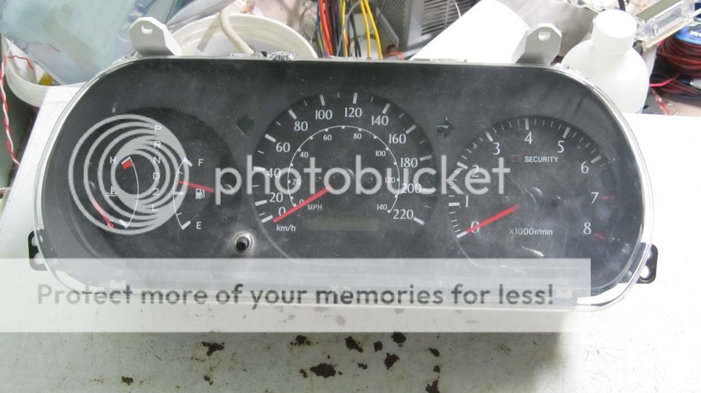
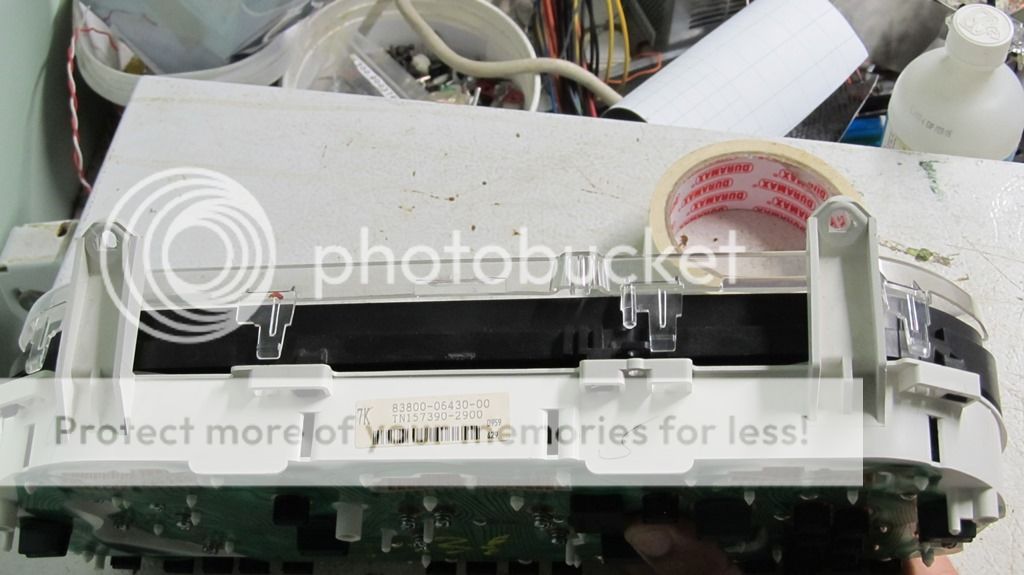
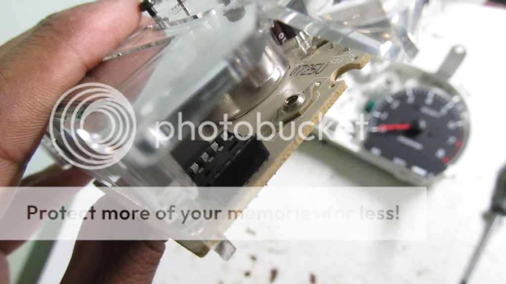
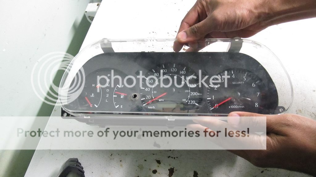
Flip it over and remove these tabs to take off the clear and black bezel.


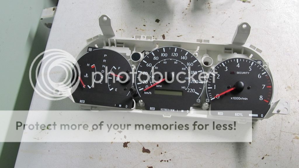
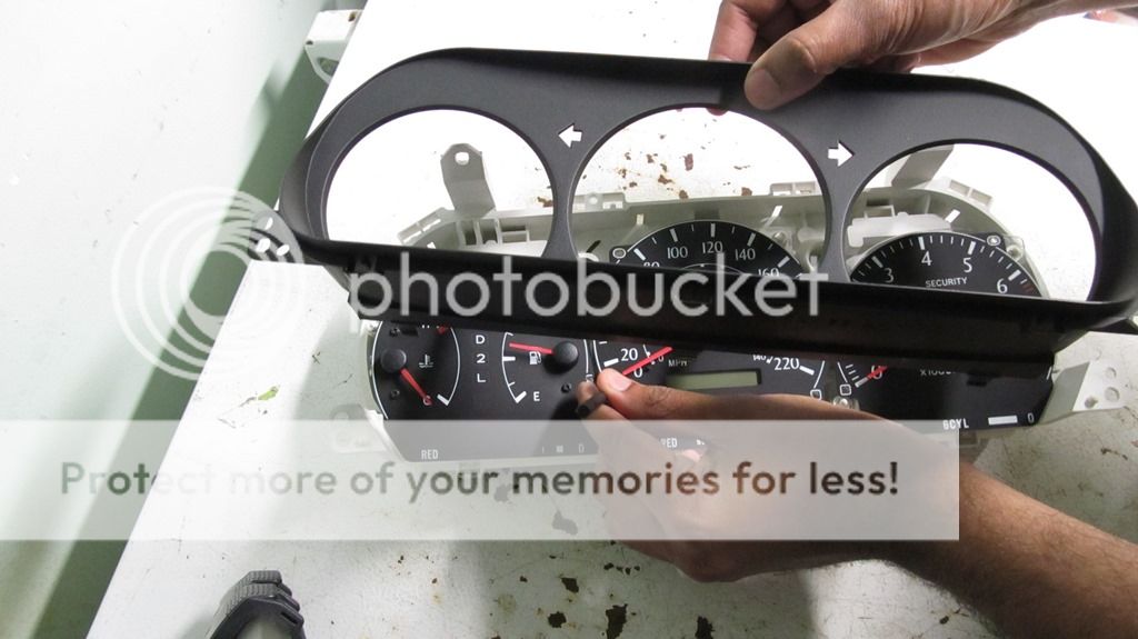
Then you should be left with something like this. Note: You don’t need to take off the needles in order to get access to the odometer chip.


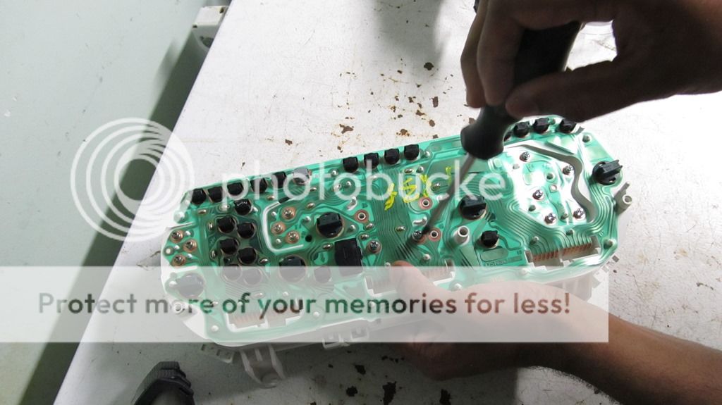
Then remove these 5 screws from the back that hold the speedometer unit to the main casing.


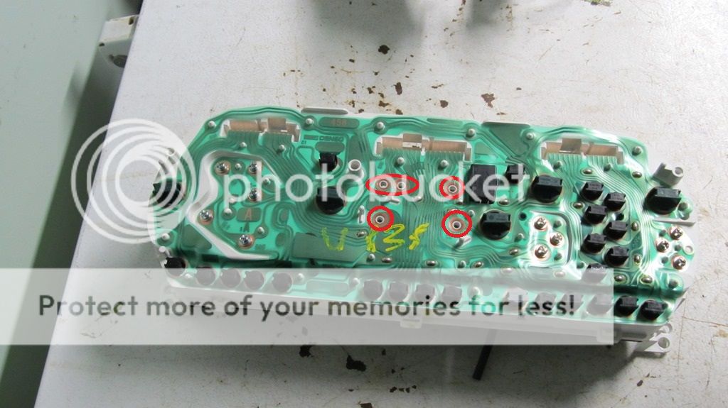
Speedometer / odometer board will just pop right out.


Here’s what the chip looks like on the PCB once you turn it over. It’s a 93C46 EEPROM chip.


De-solder the chip. Use the de-soldering pump to suck away excess solder on the joint, but be careful not to damage the solder pads, as you’ll need to re-solder to those.


Here’s the chip de-soldered from the board.


A DIP socket was soldered in to provide quick swapping of chips when testing various programs.


The next stage is to connect the EEPROM chip to the computer for reprogramming. A serial programmer can be bought off eBay, or you could build one yourself for a couple of cents.

Here’s the original schematic, which included a voltage regulator, which drew 5V directly from the serial port.

Image


It didn’t work for us, so we opted to take 5V from the computer’s power supply. There shouldn’t be an issue with this, since the grounds are common.


Here’s my home-made serial programmer, as basic as it gets.


Here’s my hacked connection to the serial port, because I ordered the wrong serial port header.


Here’s a pin-out of the serial port for the connections.

Image


Once the chip is connected and powered on, open up your serial programming software. I used PonyProg, which is a freeware that can read information from the serial port. It can be downloaded here: http://www.lancos.com/prog.html

First start with a calibration under the options menu, and then go to setup.


Set the I/O to Serial, select the COM port, and leave everything else unchecked.


Then go to device, select, microwire eeprom and select your chip type. The Camry/ ES300/ Corolla of this vintage all use the 9346.


Click the top left hand icon to read data from the device. You’ll be presented with a dump of what’s in the EEPROM chip.

The odometer readings are stored in lines 00 and 10 for these cars. As indicated below, it’s coded in hexadecimal, in a cluster of four digits, repeated three times. These are the values we have to edit. There are sometimes little symbols on the right hand side of the dump that tend to point to the last digit/ data that was changed, which can give a clue when trying to decode these chips.


If you can obtain a copy of TachSoft software, it can vastly help with the decoding process, and determining what kind of chip you have.


Decoding
In the example above, the odometer read 629,209 km. The hex values in the addresses sited above read 6D FA FF 9D. As it turns out, each of those hex digits correspond to a digit on the odometer readout by means of an inverted hex. The inverted hex is essentially 0-9, then A-F, backward as noted in this lookup table.


The first digit “6” corresponds to the thousandths column, the second digit “D” corresponds to the hundredths column, the third digit “F” corresponds to the tenths column, the middle three digits are unknown, the seventh digit “9” corresponds to the one-hundred-thousandths column and the eighth digit corresponds to the ten-thousandths column.

I haven’t yet figured out what controls the ones column, but I don’t think it matters as much as changing the first 5 columns.

If we take the inverse of each hex digit using the lookup table, put these together, you can see how the code forms the odometer reading, 629,20x km.

I made an excel sheet to calculate all the inverted hex values when I type in my desired mileage.


In my case, the desired reading is 265,650km, which corresponds to A9 AF FF D9. I need to replace the hex values in each of the three spots it’s repeated in the EEPROM code. Click edit, then Edit Buffer Enable in PonyProg to enable editing. Good idea if you saved the original chip dump in case something gets messed up during editing.


Then click the second top left button to write the new edited file to the chip. Then click Edit, Verify to verify the write was successful.


Done with the programming! Disconnect the circuit and place the chip in the correct orientation on the DIP socket on the odometer circuit board.


Reinstallation
Pretty much the reverse as taking it apart.
Replace the speedometer board into the gauge housing and screw in the 5 screws at the back of the cluster.


Replace the black bezel and wipe it from all finger-prints.


Replace the clear cover.


Reinstall the gauge cluster into the vehicle.


Turn on the vehicle and check to make sure all the gauges work. Note my new mileage reading, 265K km, which is correct for my vehicle.

Take a test drive and make sure all the gauges including the odometer works properly.


Now you can sit back and enjoy your corrected mileage reading without being flagged come inspection time.
 
#5 ·
Thanks all.

How on earth did you ever figure this all out. Way over my head, that's for sure.
I followed the link in the reference who did a similar procedure on Subaru clusters. I researched and didn't find it done for Toyota, and having done a cluster swap I was motivated to investigate if the odometer can be reprogrammed.

Once I did my background research, with the help of some junkyard clusters and my electronically savy brother, we figured out the programming. It took a few tries but we finally nailed it, with the help of the TachoSoft software.

Since there are quite a few people swapping clusters, I decided to document the process in detail in an easy to follow manner. It wasn't meant to be over-your-head but more of an instructional means for one to follow along and do this at home. The process isn't that hard, all you really need is a soldering iron and a few cents for resistors and zener diodes. :thumbsup:
 
#6 ·
Wow, great DIY!

I wonder if this will work on a 9th generation Corolla ('03 - '08)? The issue with that Corolla is that Toyota designed the odometer to max-out at 300K. I'm at 263K right now and am wondering what I can do once it freezes at 300K (or maybe 299,999). I want my odometer to reflect the true and actual mileage of my Corolla after 300K. At the very least I'd like to be able to set it to Zero the second it gets to 300K, if I can't force it to start counting above 300K.

Anybody know anything about this particular issue?
 
#8 ·
I wonder if this will work on a 9th generation Corolla ('03 - '08)? The issue with that Corolla is that Toyota designed the odometer to max-out at 300K.
I've read about this issue in the thread on the Corolla forums.

If you willing to delve into the details of the remaining contents of the EEPROM chip, you could probably correct the issue.

To answer your question, the 9th Gen Corolla uses an EEPROM chip (its unclear if its the 93C46 or 93C56). The programming will differ slightly, but once you tackle that, you need to edit the fields and replace them with "F" hex characters to reset it all to zero.

Wouldn't it been easier to just swap the EEPROM chips to get your mileage correct?
I swapped to the ES300 cluster, then drove for 6 months, so the mileage from the old EEPROM wouldn't have accounted for the 10K I put on the car during that time. But yes, if your swapping clusters, you can swap EEPROM chips at the same time to negate the need for reprogramming.
 
#12 ·
Nice tutorial, I'm wondering if it could have been possible to program it in-circuit, without desoldering the EPROM? Heat and static electricity doesn't play well but adding a socket saves the need to solder it a 2nd time.

I guess make sure your soldering tip is hot to minimize the amount of time needed to melt the solder (and thus reducing the risk of heating up the chip and damage it)
 
#17 ·
Swapping from US to Can

Hi all,

Just thought I'd revive this old thread with a few new questions as I'm attempting to do this procedure on my own vehicle. I just bought a used 05 Vibe originally from the US (I'm in Canada) and I pulled a cluster from an 05 Matrix (Canadian). Yes I know this is a Toyota forum, but there's more knowledge here than over there (heck even the guys over there are linking posts from here). I'm hoping speedkar9 is still active here or someone else might have some insight into this, so here goes:

1. At first glance, I can't find an EEPROM chip on the matrix/vibe cluster. Anyone can point me in the right direction? (I honestly haven't looked at it very thoroughly yet, I'll admit)

2. If I wanted to try zzyzzx's suggestion of simply swapping out the chip from the other cluster, how would this work since one is in Miles and the other in KMs? Is that information kept in the chip or elsewhere? Would the cluster automatically convert the values for me?

These next questions aren't odometer related, but still in the spirit of programming:

3. Does anyone know how to change the outside temperature reading from F to C?

4. My Vibe is AWD and the cluster I pulled came off a FWD matrix. The AWD models have a 45L fuel tank and the FWD models have a 50L tank. When I did a quick swap of the clusters to check function and mileage, I'm pretty sure I noticed a difference in the fuel gauge (likely because of the different programming for different size tanks), any idea if this can be changed?

Lastly, if anyone knows of any other possible problem I might encounter with this cluster swap that I might not be thinking of, feel free to let me know.

Thanks!
 
#18 ·
I'm hoping speedkar9 is still active here or someone else might have some insight into this,
I'm here.

The EEPROM chip is usually buried inside the cluster, near the odometer screen or near the speedometer because they're on the same circuit internally. You will have to open it up and look for an 8 pin black chip. It might be a surface mount chip (smaller than the one I had), so desoldering might be a bit tedious and you might be better off using a chip clip.

Now I can't comment on the miles and kilometers because I haven't swapped between the two. I assume now you want the car to read in kilometers so what you can do is compare the odometer dumps between the two to see if there's a certain HEX character in the program that differs (once you've decoded the odometer and trip counters). Otherwise just reprogram the Matrix kilometers to the correct converted Vibe mileage and keep it on the same cluster.

As for the fuel gauge, I believe its electronically a potentiometer. The gauge picks up the resistance reading from the potentiometer and presents that as a position on the dial. For the Matrix gauge to work, you'd need the fuel sender unit from the Matrix's tank or vise versa. Alternatively you could try changing the motor behind the fuel gauge needle from the Vibe cluster to the Matrix cluster, or experiment with adding a resistor in the line to make the gauge more accurate.
 
#20 ·
So here I am going through my things and checking what I need to buy to do this procedure and I pull out my old old laptop only to realize it doesn't have a Serial port (I figured it was old enough that it might have one). Has anyone experimented with USB to Serial converters? Any idea if it would work for a procedure like this?
 
#21 ·
Update on my little project:

I built my serial programmer as per the tutorial in this post, and I ended up taking my 5V via a USB port (I ordered some proper breadboard jumper wires, but I got impatient, so I just tinned some leftover wires I had laying around)


I did some reading on using a USB to Serial adapter and came up with everything and nothing. Some people sweat it'll never work, others say it works fine, some say you need an FTDI chip, others say Prolific chips are slow but work, etc etc etc.... Endless varying answers, so I figured I'd try it. I bought an adapter with a Prolific 2303 chip from Staples and installed PonyProg. Did the calibration and setup, pressed Read and voila! I get something:


At this point, I'm excited. I use TachoSoft to find out the mileage and it tells me where to look, and I come up with 6B BA 7F. I'm thinking to myself that it's odd because this cluster was stuck at 299,999kms so I figured I would see a lot of the same characters (a bunch of 6's to be exact). Sure enough, I convert 6B BA 7F quickly and after a few tries on Tachosoft, I get it in the right order and it come up with 804,594kms. WOW! Ok, so maybe although the cluster freezes at 299,999kms, maybe the chip keeps updating the mileage? But even if that's the case, 800K? That's quite a lot.


I decide to ignore this abnormality and keep going. So I input my mileage into TachoSoft and write it to the chip. After verification, it comes up with "Write failed". Damn. Things were going so well (ok, maybe not, but I was in a happy place nonetheless... until now). Try again, fail. I reread the chip and some of the bits kept their changes while others didn't.

Here's where it gets weird. I'll try to keep this short since I was trying lots of things. I try to write and read a few more times and pretty much every time, random bits here and there change (sometime even those not related to mileage). A certain bit that was successfully written earlier could stay like that for a few reads then all of a sudden it changes during the next read (there were probably some writes in there too, but not on the bit in question). I also tried installing PonyProg2000 because I saw it was the newer version, and when I first read with that one, holy cow everything was different! But then at some point it starting showing me pretty much the same thing as the older version. So after messing around with that for a while, I decided to shut her down for the evening. I'll be visiting some family over the weekend, so maybe I'll bring my setup over there and see if one of their computers has a real serial port. With any luck, that'll be the only issue causing all these gremlins.

More updates to come (hopefully I haven't screwed my eeprom chip in the process)
 
#23 ·
I try to write and read a few more times and pretty much every time, random bits here and there change (sometime even those not related to mileage).
I had the exact same thing happen when I was reading from my EEPROM immobilizer chip for transponder key information in the ECU. I rewired everything from the serial port to the chip and never had a problem read/ writing to the chip again. Must have been a loose connection.
 
#22 ·
Do let us know how things go. I am stuck at 299,999 miles on my '04 Corolla and am interested to learn how to make it keep counting past this 299,999 number. I have the tripometer keeping track of my exact mileage from the moment it froze, so I'd like to get my odometer working at the exact mileage I have. Thanks.
 
#25 ·
Hey everyone, so I got this working now! Over the weekend, I got a hold of an old laptop with a serial port and got to work. So here's a quick fly-by of the whole adventure (with pictures):

Here's the original cluster on my car. From the US, I'm in Canada. I wanted to convert to KMs and Celcius.


I wasn't sure if the temp could be changed and I wanted the rest of the cluster to be Canadian too (speedometer and all the indicator lights), so I pulled a cluster off an 05 Matrix. When I plugged it in, it was already stuck at 299,999kms

*Note: This picture was taken after I tried programming with the USB-to-Serial adapter, and so it somehow changed the Canadian cluster to Fahrenheit. At least now I knew it could be changed.

When I got the laptop up and running with PonyProg, I tried reprogramming the mileage and it wouldn't work. It would actually write properly this time, but nothing changed. Then I read the help file on TachoSoft and there was a mention about the order of the HEX characters not always being the same. I also read on another forum that to change the cluster from US to Canadian, you simply had to change the last bits from F6 to F8. My chip didn't have anything like that at the end, so that's when I started really thinking I busted the chip. At this point, I got the idea to take the chip off my current cluster and see what's up (since I knew that one was ok). I read the chip and came up with this:

Sure enough, the mileage was the right, I figured out the order while I was at it, and there were those wonderful F6 bits at the end. Now I think the Canadian cluster was more around 450K instead of the 800K I first thought. So that tells me that, although the cluster stops at 299,999 the chip still seems to keep track of the actual mileage (someone on another forum stated this as well). Unfortunately, my limited knowledge in this area means I have no idea if there's a way to force the display to go above 300K, but at least anyone with this problem can just reset to 0 (***as long as it's properly noted to add 300K to what the odometer shows).

So at this point, I'm tempted to just modify this chip and slap it into the Canadian cluster, but then I chicken out because, what if it doesn't work and I'm stuck with 2 bad clusters? Crap!... Ding! The dim light that is my brain flashes. What if the other chip isn't fried, but just scrambled? I save the data from the US chip, do a quick swap, and load the data to the Canadian chip (both chip are identical BTW, I just say US/Canadian to keep track of which cluster they originally came from). Once the data is loaded as-is, I try writing and it works (ok, honestly, the whole time I was doing this project, I had issues with PonyProg. Sometimes it would write properly, sometimes it would fail. Most times, I had better luck with PonyProg2000, but sometimes I had to switch between one or the other for unknown reasons. I blame Gremlins). Once the data was written, I modified the mileage to what I wanted (105870 miles = 170381Kms) and changed the F6 bits to F8 on the last line. Here was the final result:


Plugged it in, and voila!

Ya, I know. This picture quality sucks compared to the rest. Whatever! I did it! As you might have noticed, the last digit should have been 1 but it's 3. Like the creators of TachoSoft mention on their software, the calculations are their own and might not always be accurate. Am I going to try to fiddle around with it again for 2 measly KMs? Heck no!

Final test was to take it out for a spin and make sure that 1km on the cluster was actually 1km (and that it wasn't still counting in miles). Compared it with an app on my phone and it's perfect.

Here are a few random thoughts about this project (in no particular order):
- The USB-to-Serial converter didn't work. The one I bought had a Prolific 2303 chip which shouldn't be fake (it cost 40$ at Staples), but I couldn't really get it to work. Maybe an FTDI chip would have worked better, but finding a real serial port made it just that much more enjoyable.
- The F6/F8 bits seem to be what tells the cluster what region standards to use (at least that's what I read elsewhere). So I assume that means that it tells the cluster which temperature scale to use, whether to translate the vehicle speed sensor data into miles or KM, and probably other features when this chip is used on vehicles with more features.
- When the project was done, I was tempted to lightly solder the chip to the dip socket for fear of it falling out, but it's held in there pretty tight, so I left it as-is and so far so good.
- If writing fails, try switching between PonyProg and PonyProg2000, it worked for me, although I can't say why. Also, it during the setup, you configured to SI Prog I/O, try switching to SI Prog API. It's a slower communication (although I didn't see any difference), but I had better luck with this one. Slower usually = more stable.
- Using a USB port to get the 5V worked out perfectly. It was really simple and convenient since I was using a laptop and didn't have any extra connectors off a power supply I could use.
- Pretty much any FF bit is nothing. So if you have any of those in your mileage area, it's either zero's or just plain nothing. I figure any FF's outside of the mileage area are probably empty spots for when the chip is used on a vehicle with more features. This car doesn't have much: ODO, 2xtrip, temp, belt chime, maybe a couple more things. That accounts for maybe what? less than 64 bits out of an available 128?


I think that pretty much sums things up. I've driven about 50kms since the change and so far so good. Only problem I've encountered is an LED on the cluster's PCB that goes on and off periodically, so I'll have to tear the cluster apart again soon to check the solder joint and/or the LED itself. But for everything that concerns the conversion, I'm happy with the results.

Big thanks to speedkar9 for the initial post (and figuring out all the hard stuff) and to all those in and out of this forum that helped. I'm a happy camper!
 
#26 ·
The next stage is to connect the EEPROM chip to the computer for reprogramming. A serial programmer can be bought off eBay, or you could build one yourself for a couple of cents.
[Hate to bump an old thread but this seems to be the clearinghouse for Camry odometer information...]

You might just want to buy a Willem programmer or something similar; they're available with USB interfaces so no need to mess with serial ports. Serial ports don't all source the same voltage/current so wiring things up directly could be hit-or-miss. Hence, some of the comments in this thread about looking for an older computer to use.

I see a couple of follow-up posts complaining about seeing slightly different data on each read/write. This could be a voltage mismatch or a signal integrity problem. Using a proper EEPROM programmer on USB (with the correct settings for the chip) would minimize the odds of those sorts of issues.

Based on the photo I think the attached datasheet corresponds to the part. It requires a supply voltage of 4.5V - 5.5V.

It didn’t work for us, so we opted to take 5V from the computer’s power supply. There shouldn’t be an issue with this, since the grounds are common.
This can probably source 30 amps or more, so be super careful not to short it out or connect anything backwards. :wink:

The odometer readings are stored in lines 00 and 10 for these cars. As indicated below, it’s coded in hexadecimal, in a cluster of four digits, repeated three times. These are the values we have to edit. There are sometimes little symbols on the right hand side of the dump that tend to point to the last digit/ data that was changed, which can give a clue when trying to decode these chips.

I haven’t yet figured out what controls the ones column, but I don’t think it matters as much as changing the first 5 columns.
As you may be aware, EEPROMs have a limited number of write/erase cycles before they "wear out" and start flipping bits / becoming unreliable. The Toyota engineers may have decided to handle the ones digit differently in an effort to ensure that they did not come close to the design limits for the 93C46 (~1 million cycles). This would especially be true if they wanted to reuse the same design on vehicles that are likely to run up very high counter values (e.g. diesel trucks on the kilometer scale).

The procedure for updating the 32-bit word containing the 10, 100, 1000, 10000, 100000 digits might look like:

1) Erase the word at offset 0x08-0x0b
2) Write the new word
3) Repeat for 0x0c-0x0f, 0x10-0x13
4) When reading, look for the same value repeated twice. If one word doesn't match the other two, it was interrupted while it was being updated and should be ignored.

If they wanted to avoid generating a write/erase cycle for every single mile/km (which would wear out the EEPROM 10x faster), they might have put a bitmask somewhere else in the image. The repeated values at offsets 0x00-0x07 and 0x70-0x77 look like potential candidates. The algorithm for updating the one's digit could look like:

1) Erase the word to 0xffff -> one's digit on the odometer is 0
2) Flip a single bit from 1->0 for each mile/km traveled (EEPROMs generally allow single-bit writes)
3) After 9 bits are flipped from 1->0 and we travel another mile/km, increment the 10-100000 word above, then erase the one's word to 0xffff again

In this way, there is only one full write/erase cycle for every 10 ticks instead of every 1 tick.

They might have also used a Gray code.

Best way to figure it out is to dump the chip, travel 1km, then dump again and see what changed. Or collect a couple of dumps in this thread from different users, corresponding to different mileage readings, and try to find the pattern.

I figure any FF's outside of the mileage area are probably empty spots for when the chip is used on a vehicle with more features.
Most EEPROMs are all 0xff bytes after erasing. There are probably ranges that Toyota just didn't use at all, because the EEPROM comes in a standard size and the Toyota firmware didn't need all of that storage space. They could have also left some regions empty "for future expansion" or for higher trim lines.
 

Attachments

#35 ·
Tachnosoft says that these clusters have identical 93c46 chips, but it seems to suggest the mileage is encoded differently. I'm doubtful it will work. If there's space you could install 8-pin dip sockets on the cluster and swap the chips and see what will happen. Then you can swap the chips back with ease if it doesn't work

I'd consider doing it depending on your location.
 
#32 · (Edited)
Just did this successfully on my 2007 Yaris Hatch. Here's a quick write up of my experience.

Goals:

I bought a new Canadian cluster with tach from a 2006. Currently, my new cluster only reads 171,077 km (pictured below), I wanted it to read 320,000 km.


Programming:

The 2006-07 Yaris uses an SMD version of the 93C56 EEPROM. I used an old Dell Latitude running Windows 2k, since it has a serial port. I started with a breadboard for initial testing, but l later made a permanent programmer. I made the same circuit as OP. I originally had my bench power supply power the chip, but later used 5 volts from USB.

Breadboard:
Preview of gallery image.

Final Design:
Preview of gallery image.

I was hoping to use the test clips and program the chip while in the circuit. Sadly this is not possible. You need to remove the chip from the PCB or communication will fail.

Chip Dump:

I used PonyProg2000, selecting Microwire16 and the 93C56 chip type. Unfortunately, I don’t have a dump from the exact cluster shown above, but I do have one from an identical cluster. The mileage may not match the one pictured above, but otherwise, the data and layout are the same.

Preview of gallery image.

Preview of gallery image.

According to Tachosoft the mileage is stored in line 0060 I found this to be partially true. It is stored in line 0060 but the mileage is actually stored like this:

0060: xx xx FF FF FF FF FF FF FF FF FF FF FF FF xx xx

Where the different colors are the mileage repeated. You can use the same formula laid out by speedkar9 to find the mileage. When I used the numbers given by Techosoft the mileage didn't display properly.

But after using speedkar9s formula I got the mileage correct.

Preview of gallery image.

For lines 0000–0050, I didn’t fully reverse-engineer how everything works, but it appears those addresses store the 10s digit of the odometer and the trip values. I reset all those lines to FF to start with a clean slate.


After flashing the chip, the odometer read 320,000 km, and both trip meters were reset to zero. I didn’t grab a photo at exactly 320,000, but here’s one I took after driving a few kilometers to verify operation. You can see it reads 320,003 km instead of 320,033 km previously shown.


Final Thoughts:

I've been using my new cluster for a few days and everything seems to work as it should. I'm happy with the final result. Big thanks to speekar9 for everything 🙏

Preview of gallery image.
 
#33 ·
@ecefour ,

That's great that you were able to do that with the skill and knowledge you have. I wouldn't even try as I'd have to have you there with me showing me step by step (the way I learn). Could you have set it to the exact mileage the car had (if you had kept track of that) like 320,062 kms for example, or do you have to have it set to an even number (in your case 320,000)?

Do you think you could fix the issue on the Gen 9 Corolla? The issue is that ALL Gen 9 Corollas' odometers will STOP at 299,999 (miles or kms). It was an error or design decision of the supplier who did the odometer for Toyota. I have the exact mileage of my Corolla (now almost 449,00 miles) because I knew the odometer would freeze at 299,999, so when I got to 299,998 miles (almost 10 years ago), I pulled over and drove slowly until it changed from 299,998 to 299,999. I hit the tripometer button and have kept track of the mileage ever since. Yes, I still have the car.

If you CAN fix the issue on the Gen 9 Corolla, there might be many who would hire your services to fix the issue.
 
#34 ·
Thanks John!

So it's totally possible to get the mileage exact, it's just encoded a bit differently. The reason I didn’t try to dial it in perfectly on my cluster is that most odometers aren’t truly accurate usually within about 5%.

Technically, a new set of tires won’t read the same as worn ones due to the difference in diameter—same goes for over- or under-inflated tires.

So if your car shows 300,000 km, the actual distance could realistically be anywhere from 285,000 to 315,000 km.

So for my purposes, I was satisfied getting the odometer within less than 1%—that’s close enough for me.

As for offering a correction service—if there’s demand, I’d be willing to do it for cheap. I don’t have a 9th gen Corolla myself, but if anyone knows of a used cluster stuck at the magical 299,999 km/mi, let me know. I’d love to experiment with one before working on a customer’s odometer.