

Hi everyone..
I been a lurker for years and have posted a few times, but I wanted to put this up as a solution for those that are looking to put in a aftermarket system in their 4runner but want to use the factory rear view camera (You know the nice one built into the rear gate?)
This came about when my Wife had it with the E7008 and wanted an upgrade to something more flexable and user friendly.
Anyways, let's get started here..
The factory camera built into the 4Runner as well as other models runs a 6 volt current, not 12 volt, so we need some items to make this work.
DO NOT go out and spend a fortune on voltage converters it a waste and I will show you how to make one for under a buck fifty
First off, you need a few things to start
Extra lengths of 18 gauge primary wire (white, black, red, etc)
And old VIDEO RCA cable (picture below)
From Digikey.com a 7806 transistor and heatsink (part# 497-1445-5-ND & HS278-ND, I use digikey due to very cheap and good service. these two ports cost a whopping $1.23)
20mm fuse holder from Radio Shack ($2.99) with 1.5amp fuse
shrink tube 1/8 inch
Soldering iron, tools etc..
RCA cables
![Image]()
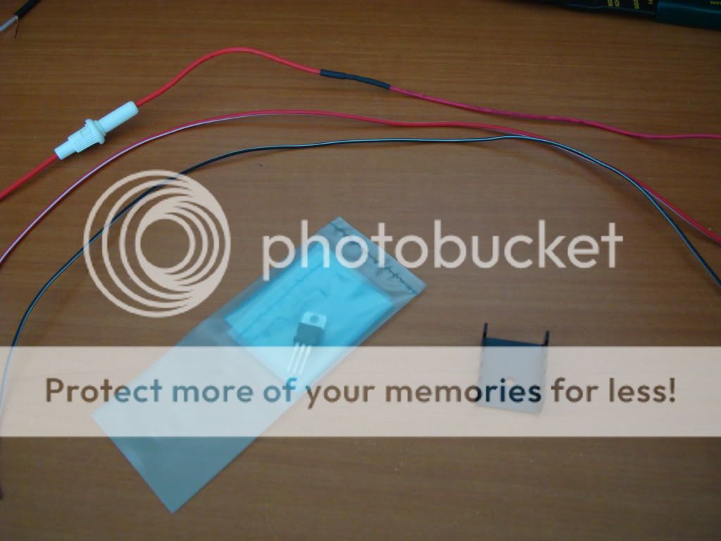
Circuits and wires / fuse holder
![Image]()
Now, on the Toyota 4Runner (I will use a 2008 model for reference) locate the 26 pin harness (B for technical reference), pins 21,22,23 & 24
this is the pinout you need
21 - Camera ground (white)
22 - Video positive (black)
23 - Video ground / sheilding (brown)
24 - Camera positive (red)
You will also need (and most aftermarket radios with built-in Nav require this)
9-pin harness (D for tech ref)
5 - Reverse wire (red/yellow)
Cut off the insulation to the wires to expose as much as possilbe (you will get about 4 inches) and snip off the wires as close to the harness connector as possible (without cutting other wires)
Now, before you go and connect anything, we need to build our voltage converter. The 7806 is a simple transistor that will convert 12v to 6v but with a high end limit of 1.5amps, perfect for a small video camera. To put this together, do the following (this requires soldering)
First using a 6-24 machine screw (about 1/4+ in length, cut a longer one if you have to) attach the 7806 to the heat sink
![Image]()
![Image]()
To solder the 7806, using s needle nose pliers, bend the end pins one up and one down, never side to side, this will crack the transistor.
Solder the wire to the pins in this order (tin the wire leads first as this will make it easier)
Left to right, pin 1, Input, solder the fuse holder to this pin (be sure to slip on some heat shrink BEFORE you start soldering)
Pin 2 - solder a 18ga ground wire
Pin 3 - Output, solder a 18ga wire to this pin.
(I would make the wires about 15 inches in length), when completed, it SHOULD look like this..
![Image]()
![Image]()
When you got it right, gently bend back the pins so they are straight.
Now for a quick test, ground the center pin wire to a nut or bolt on the car somewhere and touch the input to a live constant wire. Take your DMM and put black to where the ground is and first touch where the input wire is connected, then touch the output wire. You should see the following
![Image]()
![Image]()
Now you have made a $2.00 voltage converter. (pat self on back) This is exactly the same conversion type used inside the Toyota factory radio.
Now, for the next steps, you can either solder or use a butt connector, up to you and how comfortable you are.
After you have snipped the wires off the harnesses, strip away about 1/3 inch of wire from all 5 (including reverse wire)
Note on the reverse wire: This is where we are going to get the power for the camera, reason being is that it turn on ONLY when the car is put into reverse and it is a 12v wire. Perfect. This wire also will connect to your HU to tell it that your car is in reverse (This is what switches the HU to the rear view camera when you put car in reverse)
Here we go..
On the RCA cable, connect the center wire (positive) to the black (pin 22) wire. either solder or crimp
On the RCa cable, connect the sheilding wire (neg) to the brown (pin 23) wire. Ditto.
On the 7806, connect the input wire (fuse holder) to the reverse wire (pin 5) - I would use a butt connector and twist the reverse and 7806 input and run into one side while the aftermarket HU runs into the other
On the 7806, ground the center wire to a ground point in the car or the HU harness ground.
On the 7806, connect the output wire to the red (pin 24) positive camera wire
And finally, connect a butt connector (or solder) the white (pin 21) camera ground and run a 18ga wire to the same ground point as the 7806 center pin
MAKE SURE that if you do not shrink tube these connections, use a good elec tape (scotch 33+) and wrap them well.
Now, connect the reverse wire on the HU to the car reverse/7806 input (you put a butt connector here, remember?) and connect the RCA to the rear view camera input.
Put the car in reverse and you should see...
![Image]()
(pat self on back again) you have just wired the factory rear view camera to your new HU. You can take the 7806 and run it down toward the center console and let it hang. It does not get "hot" just a tad warm or use some 3m double sided tape and tape it against a air duct.. does not matter, just put it out of the way.
I am fairly certain the wires on this how to are the same color on other toyotas, so this should work, if not, all you need is the electrical diagram that lists the wire color and insert into the list above.
I have many years in the 12 volt world and if I can help in any way trying to figure out a way to do something with our cars, drop me a line.. Would love a new challenge.
Any questions, feel free to ask otherwise good luck..
Steve
I been a lurker for years and have posted a few times, but I wanted to put this up as a solution for those that are looking to put in a aftermarket system in their 4runner but want to use the factory rear view camera (You know the nice one built into the rear gate?)
This came about when my Wife had it with the E7008 and wanted an upgrade to something more flexable and user friendly.
Anyways, let's get started here..
The factory camera built into the 4Runner as well as other models runs a 6 volt current, not 12 volt, so we need some items to make this work.
DO NOT go out and spend a fortune on voltage converters it a waste and I will show you how to make one for under a buck fifty
First off, you need a few things to start
Extra lengths of 18 gauge primary wire (white, black, red, etc)
And old VIDEO RCA cable (picture below)
From Digikey.com a 7806 transistor and heatsink (part# 497-1445-5-ND & HS278-ND, I use digikey due to very cheap and good service. these two ports cost a whopping $1.23)
20mm fuse holder from Radio Shack ($2.99) with 1.5amp fuse
shrink tube 1/8 inch
Soldering iron, tools etc..
RCA cables

Circuits and wires / fuse holder
Now, on the Toyota 4Runner (I will use a 2008 model for reference) locate the 26 pin harness (B for technical reference), pins 21,22,23 & 24
this is the pinout you need
21 - Camera ground (white)
22 - Video positive (black)
23 - Video ground / sheilding (brown)
24 - Camera positive (red)
You will also need (and most aftermarket radios with built-in Nav require this)
9-pin harness (D for tech ref)
5 - Reverse wire (red/yellow)
Cut off the insulation to the wires to expose as much as possilbe (you will get about 4 inches) and snip off the wires as close to the harness connector as possible (without cutting other wires)
Now, before you go and connect anything, we need to build our voltage converter. The 7806 is a simple transistor that will convert 12v to 6v but with a high end limit of 1.5amps, perfect for a small video camera. To put this together, do the following (this requires soldering)
First using a 6-24 machine screw (about 1/4+ in length, cut a longer one if you have to) attach the 7806 to the heat sink


To solder the 7806, using s needle nose pliers, bend the end pins one up and one down, never side to side, this will crack the transistor.
Solder the wire to the pins in this order (tin the wire leads first as this will make it easier)
Left to right, pin 1, Input, solder the fuse holder to this pin (be sure to slip on some heat shrink BEFORE you start soldering)
Pin 2 - solder a 18ga ground wire
Pin 3 - Output, solder a 18ga wire to this pin.
(I would make the wires about 15 inches in length), when completed, it SHOULD look like this..


When you got it right, gently bend back the pins so they are straight.
Now for a quick test, ground the center pin wire to a nut or bolt on the car somewhere and touch the input to a live constant wire. Take your DMM and put black to where the ground is and first touch where the input wire is connected, then touch the output wire. You should see the following


Now you have made a $2.00 voltage converter. (pat self on back) This is exactly the same conversion type used inside the Toyota factory radio.
Now, for the next steps, you can either solder or use a butt connector, up to you and how comfortable you are.
After you have snipped the wires off the harnesses, strip away about 1/3 inch of wire from all 5 (including reverse wire)
Note on the reverse wire: This is where we are going to get the power for the camera, reason being is that it turn on ONLY when the car is put into reverse and it is a 12v wire. Perfect. This wire also will connect to your HU to tell it that your car is in reverse (This is what switches the HU to the rear view camera when you put car in reverse)
Here we go..
On the RCA cable, connect the center wire (positive) to the black (pin 22) wire. either solder or crimp
On the RCa cable, connect the sheilding wire (neg) to the brown (pin 23) wire. Ditto.
On the 7806, connect the input wire (fuse holder) to the reverse wire (pin 5) - I would use a butt connector and twist the reverse and 7806 input and run into one side while the aftermarket HU runs into the other
On the 7806, ground the center wire to a ground point in the car or the HU harness ground.
On the 7806, connect the output wire to the red (pin 24) positive camera wire
And finally, connect a butt connector (or solder) the white (pin 21) camera ground and run a 18ga wire to the same ground point as the 7806 center pin
MAKE SURE that if you do not shrink tube these connections, use a good elec tape (scotch 33+) and wrap them well.
Now, connect the reverse wire on the HU to the car reverse/7806 input (you put a butt connector here, remember?) and connect the RCA to the rear view camera input.
Put the car in reverse and you should see...

(pat self on back again) you have just wired the factory rear view camera to your new HU. You can take the 7806 and run it down toward the center console and let it hang. It does not get "hot" just a tad warm or use some 3m double sided tape and tape it against a air duct.. does not matter, just put it out of the way.
I am fairly certain the wires on this how to are the same color on other toyotas, so this should work, if not, all you need is the electrical diagram that lists the wire color and insert into the list above.
I have many years in the 12 volt world and if I can help in any way trying to figure out a way to do something with our cars, drop me a line.. Would love a new challenge.
Any questions, feel free to ask otherwise good luck..
Steve
")