
DIY: 1996 Camry Timing Belt + Waterpump + Oil Seal Change 5S-FE (GEN3) - Part 1
Part 1....
I completed this procedure at 203,000 km on my 1996 Camry 2.2L Auto (5S-FE Engine) . The timing belt, drive belts, water pump, idler and tensioner had previously been changed at 103,000 km. The cost of this service in 2001 by a local garage was $698 CDN using 100% Toyota OEM parts (ie. $200 for 3.4 hours of labour and $498 for the parts). Even though the 5S-FE four cylinder engine is non-interference, it's still in the owner's best interests to make sure the timing belt is replaced periodically. The recommended replacement interval is 100,000 km or 60,000 miles.
Disclaimer
Use this guide at your own risk! I assume no responsibility for any damage to your vehicle or personal injury as a result of following this guide. Any comments to improve the procedure will be gratefully received.
Acknowledgments
I'd like to thank the members of TN for posting their detailed timing belt replacement procedures. Without them, I probably would not have had the confidence to tackle this job on my own.
Special Tools Required
a) Harmonic balancer pulley puller (free rental available from local Parts Source)
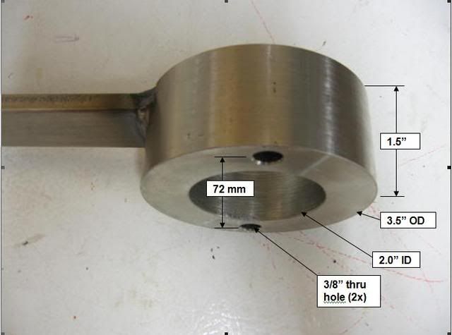
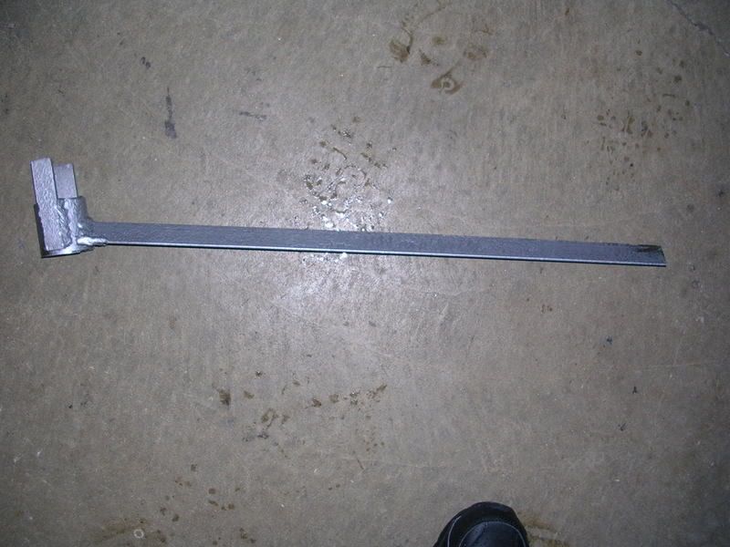
b) Crankshaft pulley holder tool. I made my own. I nicknamed it the “club”. You will see why in the photos to follow.
Time Required
It took me 14 hours from start to finish, including time to take photos, replace the timing cover gaskets and degrease the engine and all parts. If I had to do it again, I think I could reasonably pare this down to about an 8 hour task. I would recommend setting aside a weekend to do this.
![Image]()
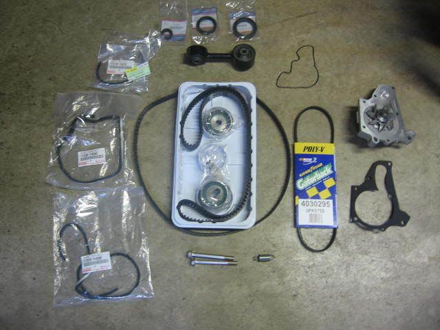
Parts Required
a) Timing Belt Kit (timing belt, water pump & gasket, idler, tensioner, crankshaft seal, camshaft seal, oil pump shaft seal) $85 USD – EBay (Ricks Engine Parts)
[EDIT - added Sept 4, 2010] The size of the above three oil seals was provided by TN member pmx007PL. They are as follows:
Crankshaft seal: 42x60x7 mm (Inside Diameter x Outside Diameter x Thickness).
Camshaft seal (timing belt side): 38x50x8 mm.
Oil pump shaft seal: 18x30x7 mm.
b) Engine Motor Torque Rod Mount $15 USD – Amazon.com (AutoPartPro)
c) Lower Engine Mount Bolts (2x) Toyota #90105-10362 $3 each.
d) Tensioner spring Toyota #90507-17003 $5
e) Oil pump o-ring gasket Toyota #15188-63010 $19.10
f) Upper timing belt cover gasket (long) Toyota #11329-74080 $8.30
g) Upper timing belt cover gasket (short) Toyota #11319-74030 $6.80
h) Lower timing belt cover gasket Toyota #11328-74060 $8.30
i) Power steering multi-V belt $7 – Parts Source
j) AC/Alternator multi V-belt $18 – Parts Source
k) 4 liters of distilled water $1
l) 4 liters of coolant $12 estimated.
Total = $190
Let's get started...
![Image]()
1. Loosen lug nuts on front right wheel. Support front of car on jack stands. Remove right front wheel.
![Image]()
2. Drain the coolant using the drain plug on the bottom of the radiator.
![Image]()
3. Remove two bolts. (10mm)
![Image]()
4. Set aside fender apron. Unclip and remove coolant overflow tank.
![Image]()
5. Pull spark plug boots and remove the spark plugs. You will need a 5/8” spark plug socket and 6” extension.
[Edit Set. 12, 2010]: This comment was added following problems experienced by TN Forum member "artie in miami". If you must leave the spark plug holes exposed for an extended period of time, particulary in a high humidity location like Miami, rust may form on the inside the cyinder walls, making it difficult or impossible to rotate the crankshaft by hand, as required in Step 47 & 48 of this procedure. If you are going to take more than one day to complete this procedure, it is recommended to squirt some engine oil into the spark plug holes and turn the engine over to coat the cylinder walls prior to proceding.
![Image]()
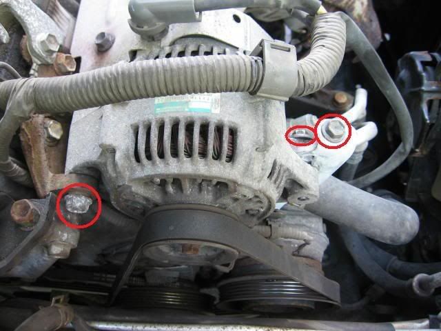
6. Loosen alternator tension. Remove drive belt. Remove two mounting bolts (14mm and 12mm).
[Edit Set. 12, 2010]: This comment was added following problems experienced by TN Forum member "artie in miami". To avoid a potential for a spark at the alternator, disconnect the poistive battery terminal before moving to Step 7. Artie wrote..."There is definately a potential for a spark at the alternator...it happened to me...the lead that connects to the alternator that has the rubber boot on it is live 12v from the battery...if it touches a ground, you blow the fuse in the box under the hood and that costs about $15...so it is a very good idea to disconnect the negative lead from the battery !"
![Image]()
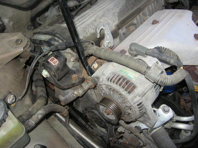
7. Pry alternator from hinge block.
![Image]()
8. Set alternator aside. Attach a ground wire to the alternator. I read that leaving the alternator ungrounded could cause problems. I am not sure if this is true.
![Image]()
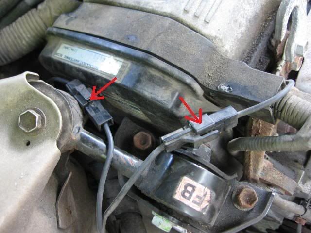
9. Disconnect two ground plugs.
![Image]()
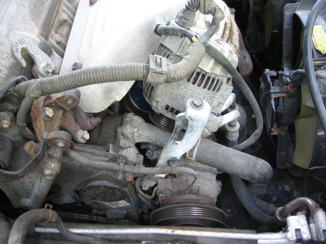
10. Remove engine torque rod mount (aka the “dog bone”). 3 bolts (14 mm).
![Image]()
11. The rubber has deteriorated (ie. original equipment). It may explain why the car vibrates slightly at idle. I ordered a new on online for $15. Be sure to order the engine torque rod mount for the 4 cylinder engine. It is my understanding that the similar part for the 6 cylinder engine is not interchangeable. [EDIT]: After installing the new mount, it did not reduce the vibration at idle.
![Image]()
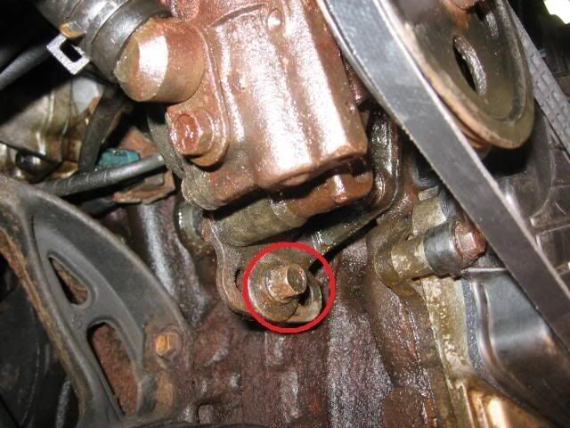
12. Remove the aluminum engine mount. Three bolts (14mm). The top bolt came out easy. The bottom two bolts were difficult to remove. The bolt heads were rusted. I found it easiest to “daisy chain” another wrench onto my 14mm wrench and remove the bolts from above. See photo below. The heads of these bolts were in rough shape, so I ordered two new bolts from Toyota (M10 x 1.25mm x 90mm) for $3 each and used anti-sieze on both the threads and bolt heads to help protect them from rusting for the next time.
![Image]()
13. Daisy chained wrenches with access from above.
![Image]()
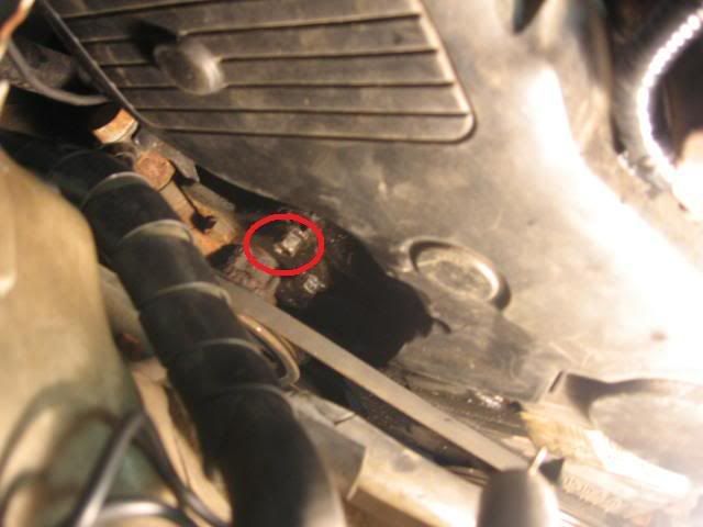
14. Remove four bolts securing the upper timing belt cover (10mm). Note that one bolt is shorter than the others, so draw a sketch so you know where the short one goes when you replace this cover.
![Image]()
15. There is a wiring harness that snaps onto the upper timing belt cover in two locations. Pinch the snaps with a needle nose pliers to release the wiring harness. Treat the wiring harness with care. The casing on mine was brittle and it cracked when I moved the harness out of the way, so I had to tape it up.
![Image]()
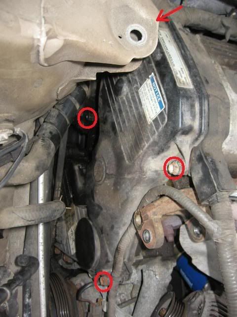
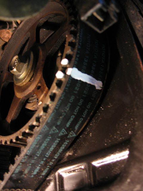
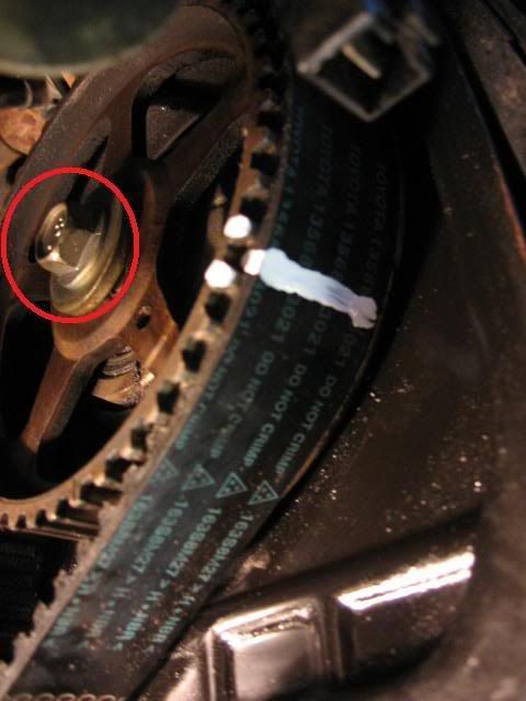
16. Remove the upper timing belt cover. Note that there is a plastic tab (see green arrow) that slides in behind a sheet metal bracket (see photo below) which secures the cover near the bottom. To release the cover, you need to move the plastic tab out from behind the sheet metal bracket by pushing the timing cover sideways at this location. It came apart relatively easy for me, but I wasted a good 20 minutes trying to install the plastic cover during installation before I figured this out. Keep this point in mind for installation. The red circles show the bolt locations. There is a hole in the plastic tab (green arrow), but no mounting bolt at this location.
![Image]()
17. The green arrow points to the sheet metal bracket which the plastic tab (also green arrow in photo above) must slide behind during installation. The red arrow points to a plastic part on the lower timing belt cover which interlocks with a mating slot in upper timing belt cover (see next photo).
![Image]()
18. The red arrow points to a “slot” in the upper timing belt cover which slides over the lower timing belt cover to seal this area.
![Image]()
![Image]()
19. Loosen the upper pivot bolt and lower adjustment bolt (12mm) on the power steering pump belt. Release the belt tension with a pinch bar and remove the belt.
![Image]()
![Image]()
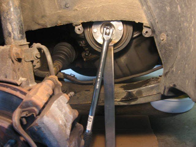
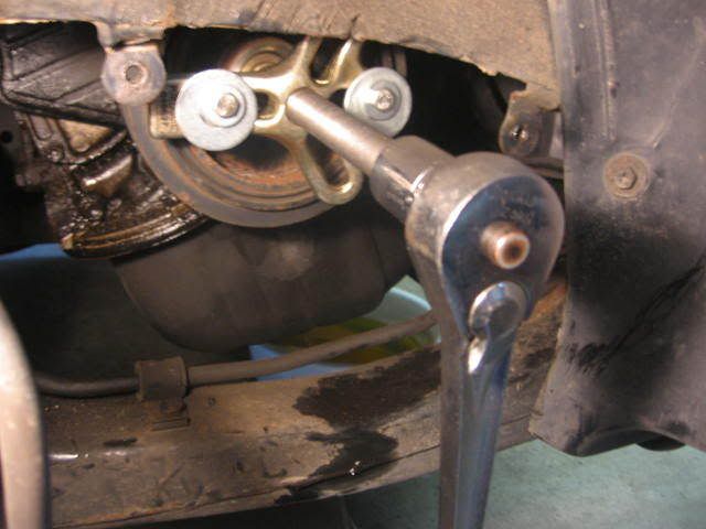
20. Remove the crankshaft pulley bolt (19mm). Note that after reading some of the problems that people have been experiencing with this step, I decided to make a special tool to hold the pulley while loosening the bolt. I nicknamed it the “club”. It consists of a round head welded to a long handle. The round head has a 3.5” OD x 2” ID x 1.5” deep with two 3/8” through holes on 72mm centers. The 17” handle is 1 1/4” x 3/8” flat bar welded to one side of the round head. I used two M6 x 1.0 x 60mm bolts to bolt the club to the pulley. I also bought a cheap 18” x ½” power bar and a set of metric impact sockets from Princess Auto to perform this task. Using the club and the ½” power bar, the crankshaft bolt was easy to remove. The 19mm impact socket was really not needed. If I had to do it again, I would not bother to buy the impact socket set.
EDIT: The crankshaft pulley bolt has a "normal" right hand thread. You need to turn the bolt counter-clockwise to loosen it.
![Image]()
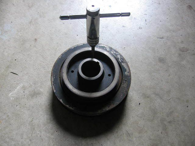
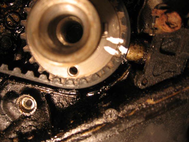
21. Note that the pulley has four holes. Two of the holes are threaded and the other two holes are not. I had to rotate the crank shaft (via the pulley bolt) to gain access to the threaded holes in order to use the club. Note that the Haynes manual says to align the timing marks at this point. I ignored this step until later on. I don’t think it is necessary for a non-interference engine such as the 5S-FE.
![Image]()
![Image]()
22. Use the harmonic balancer puller to remove the pulley. I found that the M6 x 1.0 x 60mm bolts to be long enough for this task. The rental puller did not have any bolts smaller than M8, so you are going to need to buy these bolts independently. You will also need some flat washers due to the small head size of the M6 bolts. Use the harmonic puller with the “flat” side of the arms facing outward – not as shown above.
[Edit - added Apr. 4, 2010] This point was noted by TN member Rattlin_Steele: One thing to add for anyone who read this, apparently not all crank pulleys are the same with respect to the bolt holes for the harmonic balance puller. Mine were 8mm, 1.25 pitch.
![Image]()
23. The threads in the pulley were rusted, so I re-tapped them with a M6 x 1.0 tap, gooped some anti-sieze compound into the holes and ran some bolts through to spread the compound around. This will make it easier for the next person to remove the pulley.
![Image]()
![Image]()
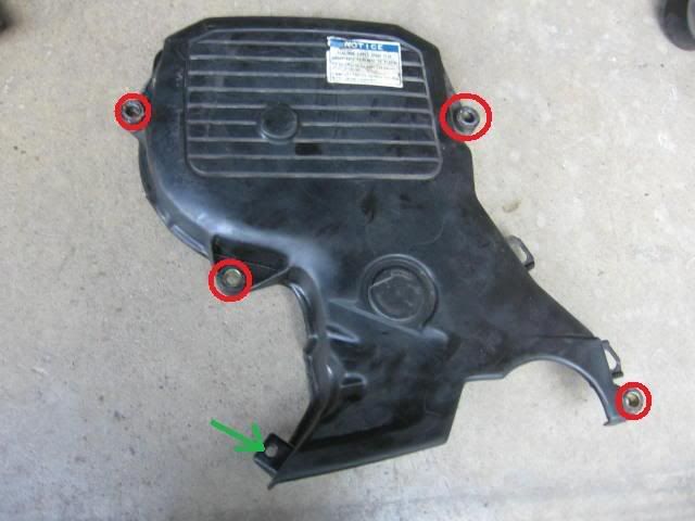
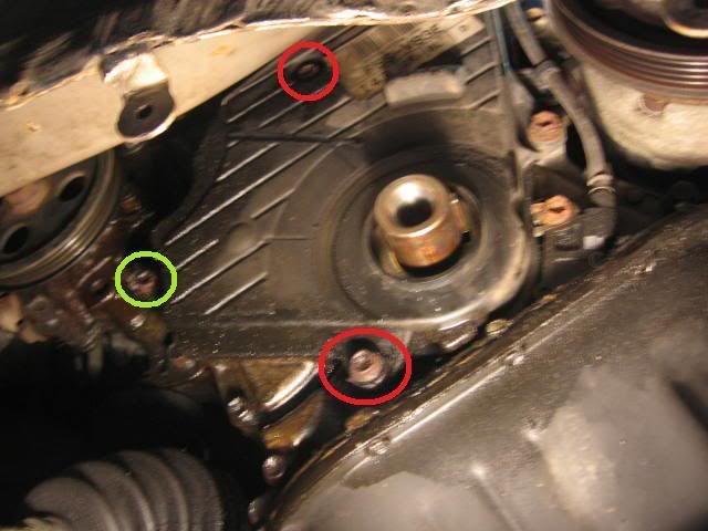
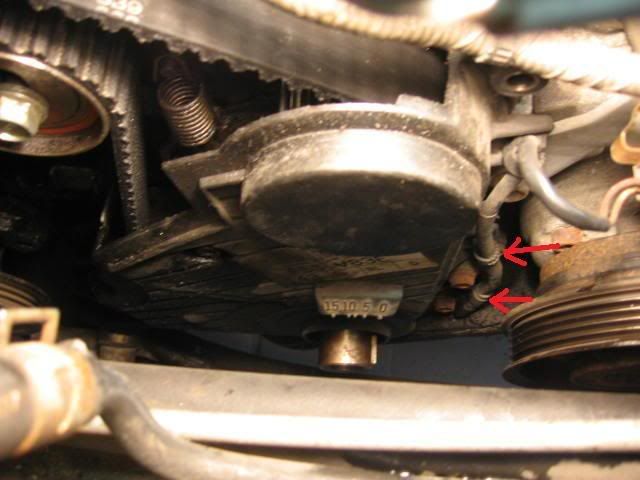
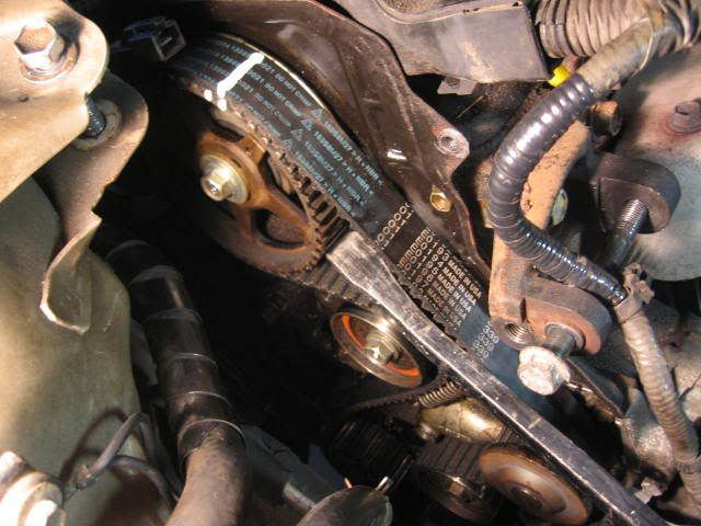
24. Remove the bolts securing the lower timing belt cover (10mm). Note that one of the bolts is longer than the others, so draw a sketch to identify where the bolts go when you remove them. The green circle is the long bolt. The red circles are the shorter bolts. Using a needle nose pliers, unclip the crank position sensor wiring harness from the lower timing cover in two locations (shown with red arrows). I found it easier to unclip the lower harness connector once the cover was unbolted and could be moved to a more accessible location.
![Image]()
![Image]()
25. Yuck! Both my timing belt covers and the area behind them was an oily mess, indicating that the oil seals are in need of replacement. The foam timing belt cover gaskets were swelled with oil and falling off in several places.
![Image]()
![Image]()
26. I cleaned up the covers with paint thinner, scraped off the old timing belt cover gaskets, and cleaned the gasket grooves with alcohol, before installing the new OEM foam gaskets. The new OEM gaskets are basically a 1/8” square black foam weather stripping with very sticky adhesive backing. The cost of the three gaskets from Toyota was about $24. I debated buying some foam weather stripping from Home Depot – but any of the self adhesive weather stripping that I have used, is too thick for this application and the adhesive is not as sticky as the Toyota OEM stuff. However, you really only need the adhesive to hold until it is installed and sandwiched in place, so I suppose that weather stripping could be used if you wanted to save some money. A photo of the covers all cleaned up with the new gaskets installed is shown.
[Edit April 4, 2010]: This comment was provided by TN Forum member pascor. Using weather stripping to substitute for the timing belt cover gasket is a very bad idea. The vast majority of man made rubber & plastics are dissolved by oil, gasoline, kerosene, grease, "mineral oil", engine oil, transmission fluid and all petroleum based solvents (which does not include alcohol), carb and brake cleaners. This includes tires. Seals must be made from materials such as Neoprene (DuPont trade name for polychloroprene) which are very resistant to all petroleum products. I'm not sure about the effect on silicon based rubber (premium spark plug wires, for example). BTW, vacuum tubing is made from Neoprene - don't ever substitute generic rubber tubing! Neoprene and silicon rubber also hold up well to high (engine) temperatures.
So, please ignore my comments above. If you need to replace the foam gaskets, it is probably best to go with OEM gaskets in this case.
![Image]()
![Image]()
27. Slide the round cupped washer (ie. belt guide) off of the crankshaft. Note that when installing this washer, the cupped side faces outward. The next step is technically not required, but I did it anyways. Using liquid paper, apply match marks to the camshaft timing pulley and crankshaft timing pulley.
![Image]()
28. With the old timing belt still installed to hold the camshaft pulley from turning, loosen the camshaft pulley bolt with a quick snap of the ratchet (14mm).
![Image]()
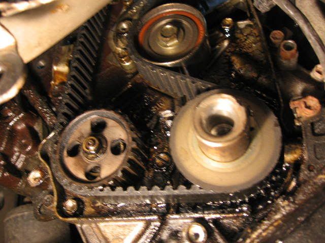
29. Pry tensioner assembly down to remove the tension on the timing belt and lock the tensioner in the “loose” position (14mm). Remove the timing belt and transfer the match marks from the old timing belt to the new timing belt. As a double check, compare old and new timing belt to ensure that they have the same number of teeth.
![Image]()
![Image]()
30. Remove the tensioner and idler pulleys (14mm bolts).
![Image]()
31. Slide the crankshaft timing pulley off the crankshaft. It should slide off easily.
![Image]()
32. Remove the camshaft pulley.
![Image]()
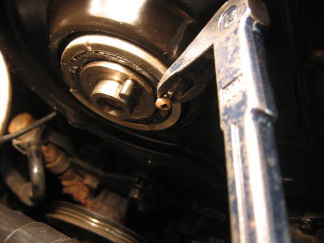
33. I carefully cut the rubber seal lip out of the camshaft seal and then tried to pry it out with a screwdriver as per the Haynes manual, but was unsuccessful. I wasted a good 30 minutes on this step. Finally, I drilled a 1/8” hole in the metal casing of the seal, being very careful not to touch the shaft or seal bore with the drill bit. Next, I screwed a small sheet metal screw into the hole and then voila! The seal easily pulled out using my cats’s paw nail puller. I found it helpful to move the power steering fluid reservoir to get a decent angle on the drill to drill the hole and I used a center punch mark to ensure that the 1/8” drill bit did not wander. This little trick came in handy later on when pulling the crankshaft seal.
Make a mental note of how far the camshaft seal is pressed into the housing before removing it. I forgot to do this and was not sure later on how far to press the new seal in.
[Edit - Added Apr. 4, 2010] The following tip was provided by TN member 71Corolla: The way I was easily able to put in the camshaft seal is I pressed in the new seal as much as I could by tapping it with a small plastic hammer (use whatever method works, but don't use anything metal). Then using the old seal, I put it against the new seal backwards, then using the cam sprocket also reversed/backwards, hold the old seal in place against the new one and thread the cam bolt in until snug. Make sure the old seal is aligned and in the center. It takes a bit of effort and fiddling to hold it all in place until the cam sprocket is snug. Then crank down the bolt and it will press in the new seal easily. Don't go crazy with tightening the bolt, just enough to ensure the seal is pressed all the way in. Saves a whole lot of frustration using this method. On that note, I have always pressed in the seal as much as it will go and never had a problem, the bore is the correct depth as far as I know, so that the seal should be seated all the way in.
![Image]()
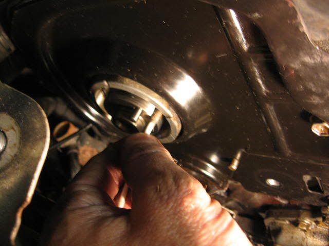
34. Clean the shaft and seal bore with a Q-tip and solvent. Lubricate the new seal ID and OD with some clean engine oil and press the seal into the housing to the same depth as noted above. There is not much room to press the seal in here. I was able to partially press the seal in by hand and then used a short piece of 2” central vacuum pipe with a wooden 2x2 and some plywood pieces wedged against the engine compartment sidewall to press the seal in the rest of the way. Even so, the seal still protruded about 1/16” from the seal bore. This was as far as I could press it in. I am not sure if the old seal protruded out this far and wish I would have made a mental note of this prior to removing the seal.
![Image]()
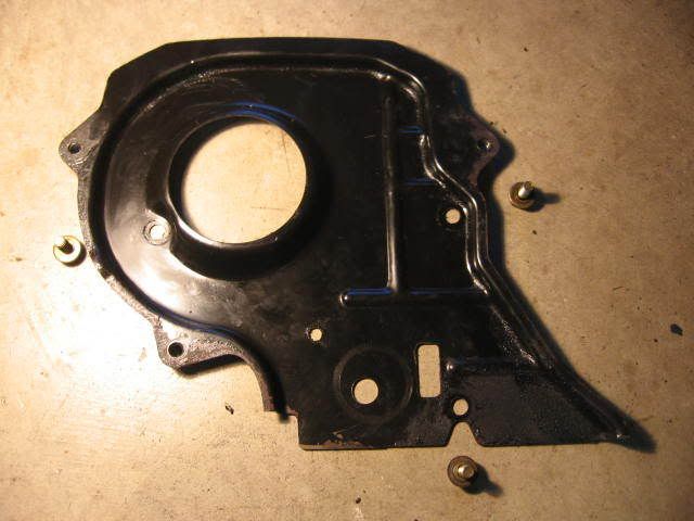
35. This step is optional. Remove the metal timing belt rear cover and clean it as well as the area behind the cover and re-install it. Three bolts (10mm).
![Image]()
![Image]()
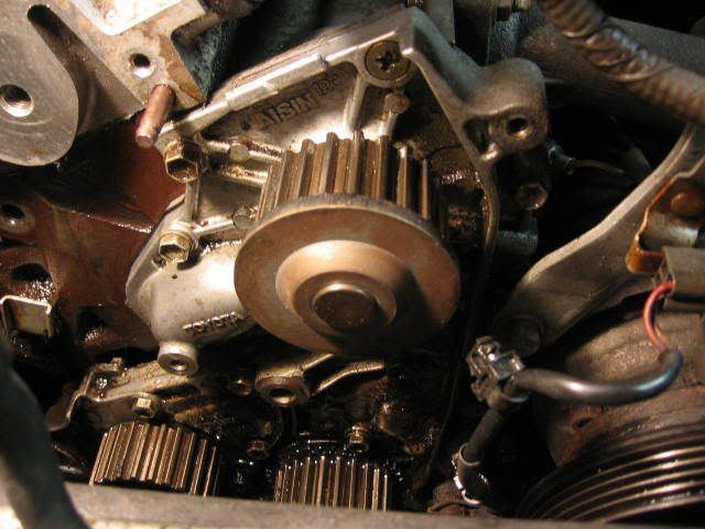
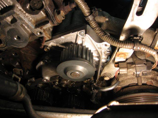
36. Before starting this step, place a catch pan under the water pump. I failed to do this and got about a ½ liter of coolant on the floor. Remove the water pump. Note that there are different length bolts. I think there are 7 bolts in total. I got sloppy on this step and did not pay attention to the different length of bolts and paid for this mistake later on by stripping one of the bolts during assembly. TIP: Remove one bolt out at a time and place it in the correct location in the new water pump, so that you don’t get mixed up later on. This sloppiness cost me an extra ½ hour and some added frustration.
![Image]()
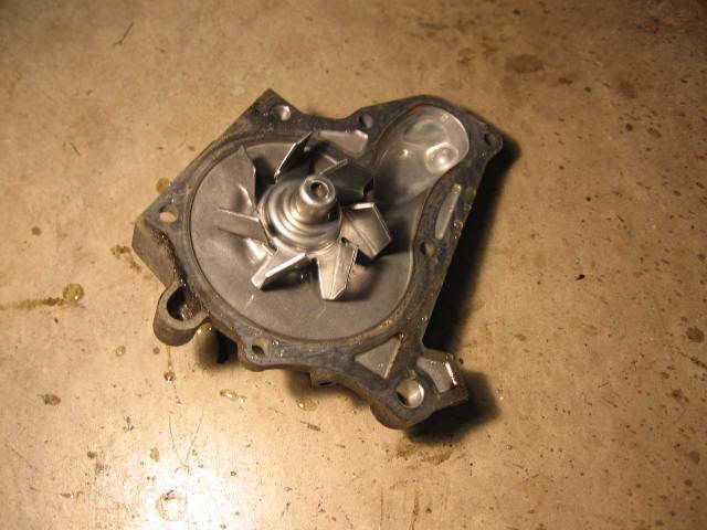
37. Install the water pump gasket and new water pump. I did not use any RTV on the water pump gasket.
[Edit Apr.3, 2010] This tip was provided by TN member 73sport. Note that I did not seal my water pump gasket and it has not leaked since. I suspect that mine was not the plain paper type, but rather the better quality gasket material with polymers to prevent it from seeping.
TIP: SEAL THE GASKETS!
All, if you end up using dry paper gaskets on any application (Oil or coolant) I recommend you seal them on all sides to preserve them.
You can do this with products such as spray on Copper Coat. Its like spraying a thin layer of sealant on all sides and edges of a gasket to keep the fluids from penatrating it. In a pinch, any gloss spray paint is better than nothing. Spray the gasket, allow it to tack, wipe the area to be installed clean with lacquer thinner and apply the gasket. It will keep it from seeping for years and make it stronger so it doesn't tear.
Note: better quality gasket materials have polymers in that that keep them from seeping and weeping oil and antifreeze. Dry paper gaskets and cork are the ones I'm refering too and should be sealed before being installed.
![Image]()
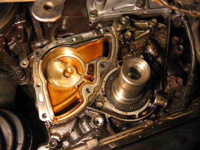
38. Remove the oil pump. Note that there are different length bolts, some with washers and some without washers. 7 bolts in total (10mm). Recommend that you make a diagram to note the correct location of the bolts. I removed mine in CCW order and laid them on the floor in the correct order.
![Image]()
![Image]()
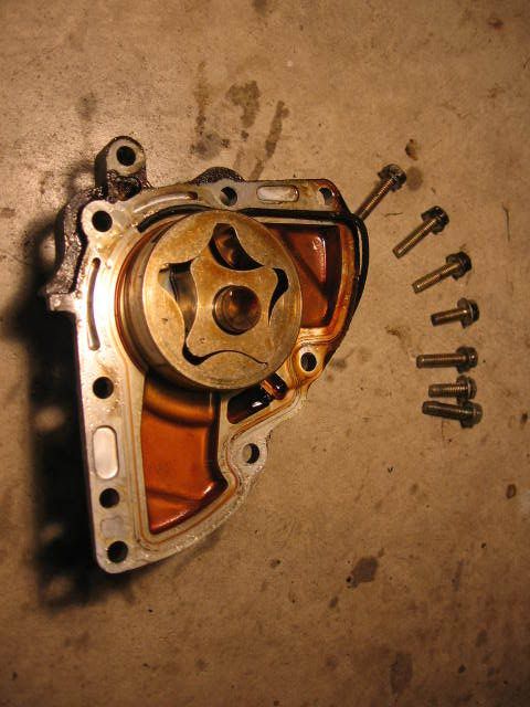
39. The o-ring gasket on my oil pump was hard and brittle. It broke as I removed the oil pump. There is a good possibility that this may have been the primary contributor to the oil leakage in this area. If you are planning to change the oil pump seal, buy a new gasket from Toyota for $19. I would highly recommend a new o-ring gasket as it is unlikely, you will be able to re-use yours. I carefully peeled off the o-ring gasket, leaving no residue. Note that there are two rotors - a drive rotor and a driven rotor. The drive rotor is attached to the shaft, but the driven rotor is loose. Be careful not to drop the driven rotor on the floor when removing the oil pump. Clean the oil pump.
Click on the link below to go to Part 2 of this Procedure....
http://www.toyotanation.com/forum/showthread.php?t=264429
Part 1....
I completed this procedure at 203,000 km on my 1996 Camry 2.2L Auto (5S-FE Engine) . The timing belt, drive belts, water pump, idler and tensioner had previously been changed at 103,000 km. The cost of this service in 2001 by a local garage was $698 CDN using 100% Toyota OEM parts (ie. $200 for 3.4 hours of labour and $498 for the parts). Even though the 5S-FE four cylinder engine is non-interference, it's still in the owner's best interests to make sure the timing belt is replaced periodically. The recommended replacement interval is 100,000 km or 60,000 miles.
Disclaimer
Use this guide at your own risk! I assume no responsibility for any damage to your vehicle or personal injury as a result of following this guide. Any comments to improve the procedure will be gratefully received.
Acknowledgments
I'd like to thank the members of TN for posting their detailed timing belt replacement procedures. Without them, I probably would not have had the confidence to tackle this job on my own.
Special Tools Required
a) Harmonic balancer pulley puller (free rental available from local Parts Source)
b) Crankshaft pulley holder tool. I made my own. I nicknamed it the “club”. You will see why in the photos to follow.
Time Required
It took me 14 hours from start to finish, including time to take photos, replace the timing cover gaskets and degrease the engine and all parts. If I had to do it again, I think I could reasonably pare this down to about an 8 hour task. I would recommend setting aside a weekend to do this.
Parts Required
a) Timing Belt Kit (timing belt, water pump & gasket, idler, tensioner, crankshaft seal, camshaft seal, oil pump shaft seal) $85 USD – EBay (Ricks Engine Parts)
[EDIT - added Sept 4, 2010] The size of the above three oil seals was provided by TN member pmx007PL. They are as follows:
Crankshaft seal: 42x60x7 mm (Inside Diameter x Outside Diameter x Thickness).
Camshaft seal (timing belt side): 38x50x8 mm.
Oil pump shaft seal: 18x30x7 mm.
b) Engine Motor Torque Rod Mount $15 USD – Amazon.com (AutoPartPro)
c) Lower Engine Mount Bolts (2x) Toyota #90105-10362 $3 each.
d) Tensioner spring Toyota #90507-17003 $5
e) Oil pump o-ring gasket Toyota #15188-63010 $19.10
f) Upper timing belt cover gasket (long) Toyota #11329-74080 $8.30
g) Upper timing belt cover gasket (short) Toyota #11319-74030 $6.80
h) Lower timing belt cover gasket Toyota #11328-74060 $8.30
i) Power steering multi-V belt $7 – Parts Source
j) AC/Alternator multi V-belt $18 – Parts Source
k) 4 liters of distilled water $1
l) 4 liters of coolant $12 estimated.
Total = $190
Let's get started...
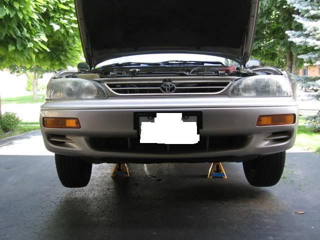
1. Loosen lug nuts on front right wheel. Support front of car on jack stands. Remove right front wheel.
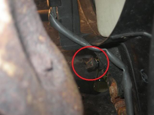
2. Drain the coolant using the drain plug on the bottom of the radiator.
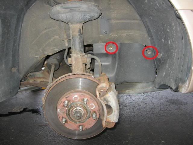
3. Remove two bolts. (10mm)
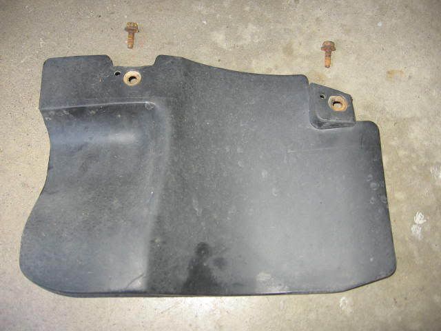
4. Set aside fender apron. Unclip and remove coolant overflow tank.
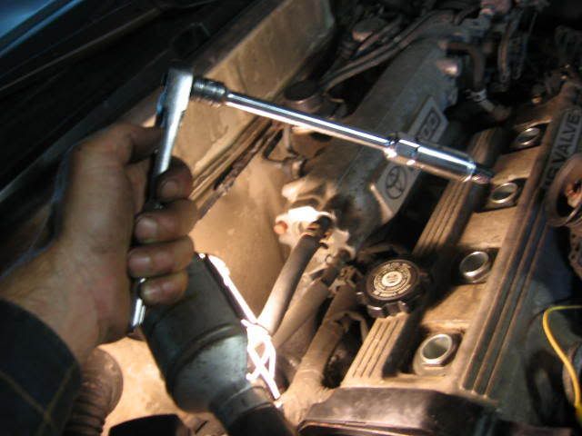
5. Pull spark plug boots and remove the spark plugs. You will need a 5/8” spark plug socket and 6” extension.
[Edit Set. 12, 2010]: This comment was added following problems experienced by TN Forum member "artie in miami". If you must leave the spark plug holes exposed for an extended period of time, particulary in a high humidity location like Miami, rust may form on the inside the cyinder walls, making it difficult or impossible to rotate the crankshaft by hand, as required in Step 47 & 48 of this procedure. If you are going to take more than one day to complete this procedure, it is recommended to squirt some engine oil into the spark plug holes and turn the engine over to coat the cylinder walls prior to proceding.
6. Loosen alternator tension. Remove drive belt. Remove two mounting bolts (14mm and 12mm).
[Edit Set. 12, 2010]: This comment was added following problems experienced by TN Forum member "artie in miami". To avoid a potential for a spark at the alternator, disconnect the poistive battery terminal before moving to Step 7. Artie wrote..."There is definately a potential for a spark at the alternator...it happened to me...the lead that connects to the alternator that has the rubber boot on it is live 12v from the battery...if it touches a ground, you blow the fuse in the box under the hood and that costs about $15...so it is a very good idea to disconnect the negative lead from the battery !"
7. Pry alternator from hinge block.
8. Set alternator aside. Attach a ground wire to the alternator. I read that leaving the alternator ungrounded could cause problems. I am not sure if this is true.
9. Disconnect two ground plugs.
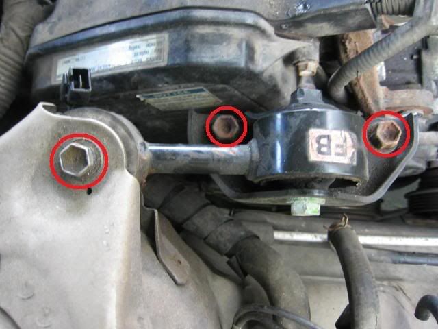
10. Remove engine torque rod mount (aka the “dog bone”). 3 bolts (14 mm).
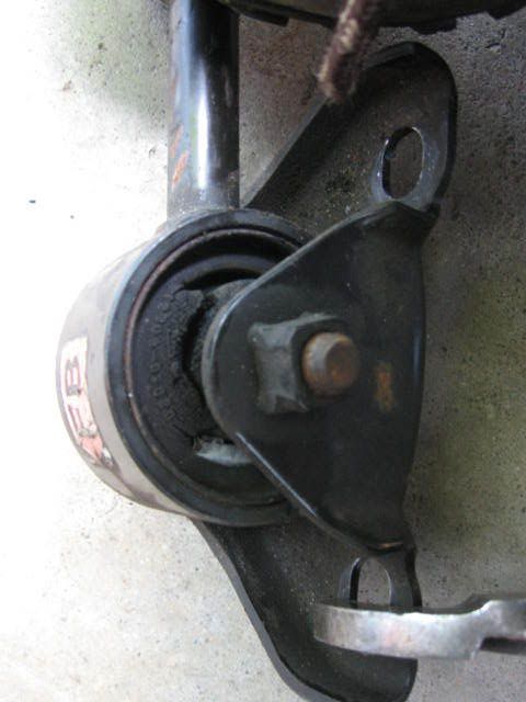
11. The rubber has deteriorated (ie. original equipment). It may explain why the car vibrates slightly at idle. I ordered a new on online for $15. Be sure to order the engine torque rod mount for the 4 cylinder engine. It is my understanding that the similar part for the 6 cylinder engine is not interchangeable. [EDIT]: After installing the new mount, it did not reduce the vibration at idle.
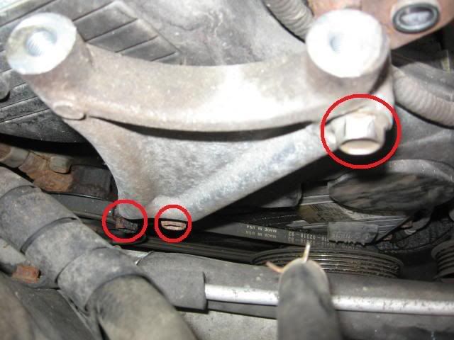
12. Remove the aluminum engine mount. Three bolts (14mm). The top bolt came out easy. The bottom two bolts were difficult to remove. The bolt heads were rusted. I found it easiest to “daisy chain” another wrench onto my 14mm wrench and remove the bolts from above. See photo below. The heads of these bolts were in rough shape, so I ordered two new bolts from Toyota (M10 x 1.25mm x 90mm) for $3 each and used anti-sieze on both the threads and bolt heads to help protect them from rusting for the next time.
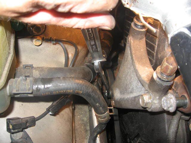
13. Daisy chained wrenches with access from above.
14. Remove four bolts securing the upper timing belt cover (10mm). Note that one bolt is shorter than the others, so draw a sketch so you know where the short one goes when you replace this cover.
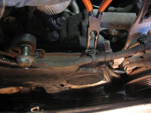
15. There is a wiring harness that snaps onto the upper timing belt cover in two locations. Pinch the snaps with a needle nose pliers to release the wiring harness. Treat the wiring harness with care. The casing on mine was brittle and it cracked when I moved the harness out of the way, so I had to tape it up.
16. Remove the upper timing belt cover. Note that there is a plastic tab (see green arrow) that slides in behind a sheet metal bracket (see photo below) which secures the cover near the bottom. To release the cover, you need to move the plastic tab out from behind the sheet metal bracket by pushing the timing cover sideways at this location. It came apart relatively easy for me, but I wasted a good 20 minutes trying to install the plastic cover during installation before I figured this out. Keep this point in mind for installation. The red circles show the bolt locations. There is a hole in the plastic tab (green arrow), but no mounting bolt at this location.
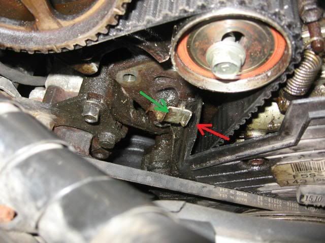
17. The green arrow points to the sheet metal bracket which the plastic tab (also green arrow in photo above) must slide behind during installation. The red arrow points to a plastic part on the lower timing belt cover which interlocks with a mating slot in upper timing belt cover (see next photo).

18. The red arrow points to a “slot” in the upper timing belt cover which slides over the lower timing belt cover to seal this area.
19. Loosen the upper pivot bolt and lower adjustment bolt (12mm) on the power steering pump belt. Release the belt tension with a pinch bar and remove the belt.
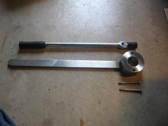

20. Remove the crankshaft pulley bolt (19mm). Note that after reading some of the problems that people have been experiencing with this step, I decided to make a special tool to hold the pulley while loosening the bolt. I nicknamed it the “club”. It consists of a round head welded to a long handle. The round head has a 3.5” OD x 2” ID x 1.5” deep with two 3/8” through holes on 72mm centers. The 17” handle is 1 1/4” x 3/8” flat bar welded to one side of the round head. I used two M6 x 1.0 x 60mm bolts to bolt the club to the pulley. I also bought a cheap 18” x ½” power bar and a set of metric impact sockets from Princess Auto to perform this task. Using the club and the ½” power bar, the crankshaft bolt was easy to remove. The 19mm impact socket was really not needed. If I had to do it again, I would not bother to buy the impact socket set.
EDIT: The crankshaft pulley bolt has a "normal" right hand thread. You need to turn the bolt counter-clockwise to loosen it.
21. Note that the pulley has four holes. Two of the holes are threaded and the other two holes are not. I had to rotate the crank shaft (via the pulley bolt) to gain access to the threaded holes in order to use the club. Note that the Haynes manual says to align the timing marks at this point. I ignored this step until later on. I don’t think it is necessary for a non-interference engine such as the 5S-FE.

22. Use the harmonic balancer puller to remove the pulley. I found that the M6 x 1.0 x 60mm bolts to be long enough for this task. The rental puller did not have any bolts smaller than M8, so you are going to need to buy these bolts independently. You will also need some flat washers due to the small head size of the M6 bolts. Use the harmonic puller with the “flat” side of the arms facing outward – not as shown above.
[Edit - added Apr. 4, 2010] This point was noted by TN member Rattlin_Steele: One thing to add for anyone who read this, apparently not all crank pulleys are the same with respect to the bolt holes for the harmonic balance puller. Mine were 8mm, 1.25 pitch.
23. The threads in the pulley were rusted, so I re-tapped them with a M6 x 1.0 tap, gooped some anti-sieze compound into the holes and ran some bolts through to spread the compound around. This will make it easier for the next person to remove the pulley.
24. Remove the bolts securing the lower timing belt cover (10mm). Note that one of the bolts is longer than the others, so draw a sketch to identify where the bolts go when you remove them. The green circle is the long bolt. The red circles are the shorter bolts. Using a needle nose pliers, unclip the crank position sensor wiring harness from the lower timing cover in two locations (shown with red arrows). I found it easier to unclip the lower harness connector once the cover was unbolted and could be moved to a more accessible location.
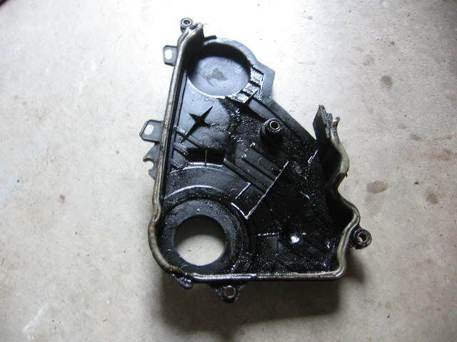
25. Yuck! Both my timing belt covers and the area behind them was an oily mess, indicating that the oil seals are in need of replacement. The foam timing belt cover gaskets were swelled with oil and falling off in several places.
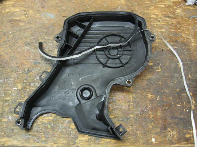
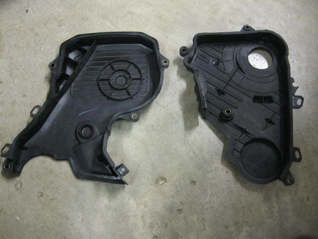
26. I cleaned up the covers with paint thinner, scraped off the old timing belt cover gaskets, and cleaned the gasket grooves with alcohol, before installing the new OEM foam gaskets. The new OEM gaskets are basically a 1/8” square black foam weather stripping with very sticky adhesive backing. The cost of the three gaskets from Toyota was about $24. I debated buying some foam weather stripping from Home Depot – but any of the self adhesive weather stripping that I have used, is too thick for this application and the adhesive is not as sticky as the Toyota OEM stuff. However, you really only need the adhesive to hold until it is installed and sandwiched in place, so I suppose that weather stripping could be used if you wanted to save some money. A photo of the covers all cleaned up with the new gaskets installed is shown.
[Edit April 4, 2010]: This comment was provided by TN Forum member pascor. Using weather stripping to substitute for the timing belt cover gasket is a very bad idea. The vast majority of man made rubber & plastics are dissolved by oil, gasoline, kerosene, grease, "mineral oil", engine oil, transmission fluid and all petroleum based solvents (which does not include alcohol), carb and brake cleaners. This includes tires. Seals must be made from materials such as Neoprene (DuPont trade name for polychloroprene) which are very resistant to all petroleum products. I'm not sure about the effect on silicon based rubber (premium spark plug wires, for example). BTW, vacuum tubing is made from Neoprene - don't ever substitute generic rubber tubing! Neoprene and silicon rubber also hold up well to high (engine) temperatures.
So, please ignore my comments above. If you need to replace the foam gaskets, it is probably best to go with OEM gaskets in this case.
27. Slide the round cupped washer (ie. belt guide) off of the crankshaft. Note that when installing this washer, the cupped side faces outward. The next step is technically not required, but I did it anyways. Using liquid paper, apply match marks to the camshaft timing pulley and crankshaft timing pulley.
28. With the old timing belt still installed to hold the camshaft pulley from turning, loosen the camshaft pulley bolt with a quick snap of the ratchet (14mm).
29. Pry tensioner assembly down to remove the tension on the timing belt and lock the tensioner in the “loose” position (14mm). Remove the timing belt and transfer the match marks from the old timing belt to the new timing belt. As a double check, compare old and new timing belt to ensure that they have the same number of teeth.
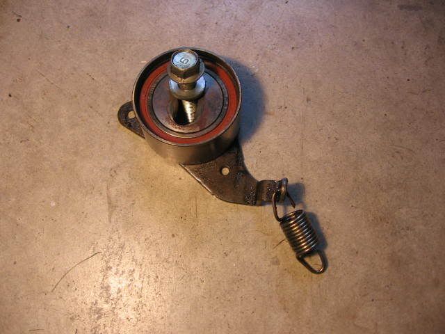
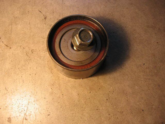
30. Remove the tensioner and idler pulleys (14mm bolts).
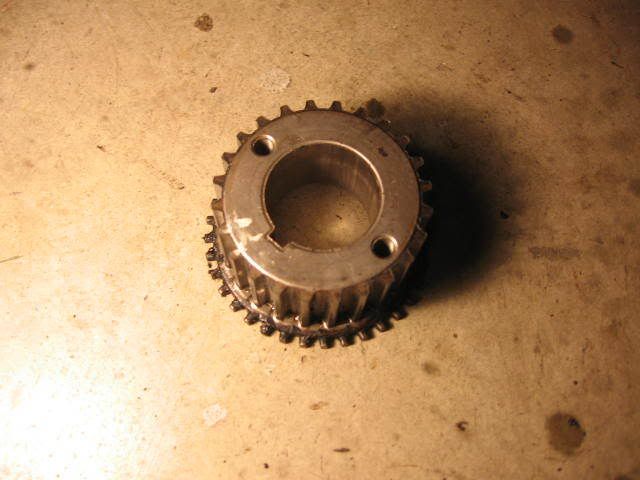
31. Slide the crankshaft timing pulley off the crankshaft. It should slide off easily.
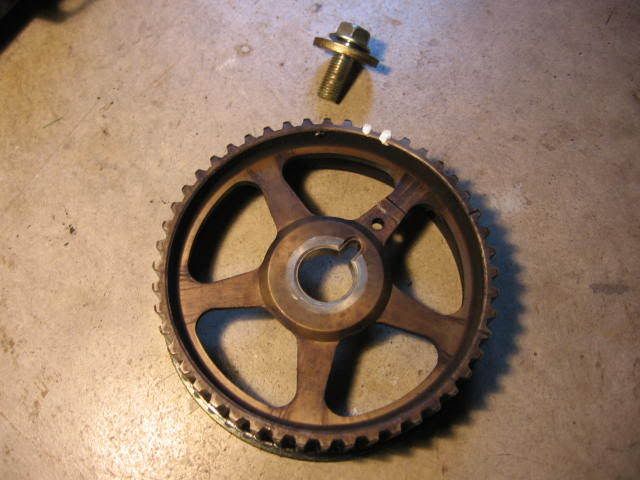
32. Remove the camshaft pulley.
33. I carefully cut the rubber seal lip out of the camshaft seal and then tried to pry it out with a screwdriver as per the Haynes manual, but was unsuccessful. I wasted a good 30 minutes on this step. Finally, I drilled a 1/8” hole in the metal casing of the seal, being very careful not to touch the shaft or seal bore with the drill bit. Next, I screwed a small sheet metal screw into the hole and then voila! The seal easily pulled out using my cats’s paw nail puller. I found it helpful to move the power steering fluid reservoir to get a decent angle on the drill to drill the hole and I used a center punch mark to ensure that the 1/8” drill bit did not wander. This little trick came in handy later on when pulling the crankshaft seal.
Make a mental note of how far the camshaft seal is pressed into the housing before removing it. I forgot to do this and was not sure later on how far to press the new seal in.
[Edit - Added Apr. 4, 2010] The following tip was provided by TN member 71Corolla: The way I was easily able to put in the camshaft seal is I pressed in the new seal as much as I could by tapping it with a small plastic hammer (use whatever method works, but don't use anything metal). Then using the old seal, I put it against the new seal backwards, then using the cam sprocket also reversed/backwards, hold the old seal in place against the new one and thread the cam bolt in until snug. Make sure the old seal is aligned and in the center. It takes a bit of effort and fiddling to hold it all in place until the cam sprocket is snug. Then crank down the bolt and it will press in the new seal easily. Don't go crazy with tightening the bolt, just enough to ensure the seal is pressed all the way in. Saves a whole lot of frustration using this method. On that note, I have always pressed in the seal as much as it will go and never had a problem, the bore is the correct depth as far as I know, so that the seal should be seated all the way in.
34. Clean the shaft and seal bore with a Q-tip and solvent. Lubricate the new seal ID and OD with some clean engine oil and press the seal into the housing to the same depth as noted above. There is not much room to press the seal in here. I was able to partially press the seal in by hand and then used a short piece of 2” central vacuum pipe with a wooden 2x2 and some plywood pieces wedged against the engine compartment sidewall to press the seal in the rest of the way. Even so, the seal still protruded about 1/16” from the seal bore. This was as far as I could press it in. I am not sure if the old seal protruded out this far and wish I would have made a mental note of this prior to removing the seal.
35. This step is optional. Remove the metal timing belt rear cover and clean it as well as the area behind the cover and re-install it. Three bolts (10mm).
36. Before starting this step, place a catch pan under the water pump. I failed to do this and got about a ½ liter of coolant on the floor. Remove the water pump. Note that there are different length bolts. I think there are 7 bolts in total. I got sloppy on this step and did not pay attention to the different length of bolts and paid for this mistake later on by stripping one of the bolts during assembly. TIP: Remove one bolt out at a time and place it in the correct location in the new water pump, so that you don’t get mixed up later on. This sloppiness cost me an extra ½ hour and some added frustration.
37. Install the water pump gasket and new water pump. I did not use any RTV on the water pump gasket.
[Edit Apr.3, 2010] This tip was provided by TN member 73sport. Note that I did not seal my water pump gasket and it has not leaked since. I suspect that mine was not the plain paper type, but rather the better quality gasket material with polymers to prevent it from seeping.
TIP: SEAL THE GASKETS!
All, if you end up using dry paper gaskets on any application (Oil or coolant) I recommend you seal them on all sides to preserve them.
You can do this with products such as spray on Copper Coat. Its like spraying a thin layer of sealant on all sides and edges of a gasket to keep the fluids from penatrating it. In a pinch, any gloss spray paint is better than nothing. Spray the gasket, allow it to tack, wipe the area to be installed clean with lacquer thinner and apply the gasket. It will keep it from seeping for years and make it stronger so it doesn't tear.
Note: better quality gasket materials have polymers in that that keep them from seeping and weeping oil and antifreeze. Dry paper gaskets and cork are the ones I'm refering too and should be sealed before being installed.

38. Remove the oil pump. Note that there are different length bolts, some with washers and some without washers. 7 bolts in total (10mm). Recommend that you make a diagram to note the correct location of the bolts. I removed mine in CCW order and laid them on the floor in the correct order.
39. The o-ring gasket on my oil pump was hard and brittle. It broke as I removed the oil pump. There is a good possibility that this may have been the primary contributor to the oil leakage in this area. If you are planning to change the oil pump seal, buy a new gasket from Toyota for $19. I would highly recommend a new o-ring gasket as it is unlikely, you will be able to re-use yours. I carefully peeled off the o-ring gasket, leaving no residue. Note that there are two rotors - a drive rotor and a driven rotor. The drive rotor is attached to the shaft, but the driven rotor is loose. Be careful not to drop the driven rotor on the floor when removing the oil pump. Clean the oil pump.
Click on the link below to go to Part 2 of this Procedure....
http://www.toyotanation.com/forum/showthread.php?t=264429