Toyota Forum banner
23K views 17 replies 8 participants last post by  Previologist  
#1 · (Edited)
Wondering if anyone would be interested in details of how I fixed my Cruise control actuator.
The problem showed up on my 1996 DX SC. It was first noticed as an occasional drop out of cruise with the subsequent 5 flashes of the cruise dash light. It kept happening more frequently until cruise would hardly stay on at all.
Troubleshooting using the jumper technique of the shop manual showed codes that point to the actuator drawing too much current, but there were other possibilities. I finally narrowed it down to the CC actuator by swapping it to my 95 LE SC where it dropped out the same way. I bought a used CC actuator on ebay for only $65, but I think it was the only one in existence because parts for SCs are getting scarce (the non-SC actuators are slightly different and a little easier to find). With that one in hand, I felt confident to go forensic on my 95 actuator. I tested its motor and lockup clutch function by applying 12v to the connector pins according to my Electrical Schematics Manual and it worked smoothly and quietly with the motor drawing about 0.3 amp.
(EDIT, 10-11-2015, Caution: the shop manual has errors in pin assignments for the test...I am making a post on this)
Then tested the one from my 96. It ran noisy and rough, drawing about 1.7 amp. Long story short, the brushes had worn down and their pressure on the commutator was uneven. I purchased the smallest brushes I could find from the nearby Ace hardware store and modified them to fit, reassembled the motor to the actuator and my previa cruise is again working flawlessly. I took some pictures and can give more details if anyone is interested.


The actuator is over $1300 from the dealer, and it is a shame to toss one just because of a couple of inexpensive brushes.


I have had 5 previas, 91 to 96 and do all the maintenance on them myself. My 96 DX was purchased at 20k miles with a flood salvage title and now has 159k miles on it and my 95 LE SC was purchased at 47k miles and now has 209k miles on it.
 
#3 ·
Good sleuthing.

I have no idea if the actuator is in the control stick off the steering wheel... but if it is then that part is widely available of similar vintage Camry's and 4runners. At the stick on the 95 SC model previas. The older prevs have a different controller and I'm not sure if that was used on other yotas.

Another note, for many drivers the "dropping" of cruise results from low brake fluid. This is an issue the pops up at this time of year as temps are getting colder and brake fluid becomes more dense...
 
#6 · (Edited)
Cruise Actuator Fix Part 1

EDIT 10-18-2015 Now applicable for all Previas, NON-SC and SC

If your cruise acts like mine did, then you should read on. Fixing it may be as simple as replacing the motor brushes.

Mine engaged for a time (split second to minutes) then dropped out as the actuator magnetic clutch released, and the Cruise dash lamp flashed slowly 5 times. At first, it only did it sometimes, but it got worse for a couple of years until it would not stay on at all. If your’s does this, then there is a good chance the fault is NOT in the many other possible components of the Cruise system. If it doesn’t engage but flashes 5 times, it still might be the actuator brushes, but there may be other problems not covered here.

If you have the engage/drop out/5 flashes, I suggest you:
(This Post, Part 1)
1. Read Codes
2. If you have code 11 and/or 13, Remove Actuator
3. Clean Cable
4. Bench Test Actuator
(Next Post, Part 2)
5. If Actuator has the bad brushes signature from your testing, Replace Actuator Brushes
6. Reinstall, Clear Codes, Road Test, Fixed?

I’ll take these one at a time after covering general info

GENERAL:
The actuator is under the dash above the accelerator pedal and is nearly identical for SC and NON-SC Previas. I have tested both. The mounting is the same but the electrical connector and lever arm length is different. This may be due to the increased load of 3 throttle cables in the SC instead of 2 in NON-SC Previa.
The SC actuator's part number is 88002-28080. This is currently specified for ALL SC models from 94 to 97. The list below is what is specified as replacement parts.

88002-28080 Specified for all 96 and 97 (all models are SC)
88002-28080 Specified for all 94 and 95 SC
88002-28071 Specified for all 94 and 95 non-SC
88002-28070 Specified for all 93 (all models are non-SC)
88002-28050 Specified for all 91 and 92 (all models are non-SC)

The Cruise module (also called the cruise ECU or computer) that runs the actuator also changes but not necessarily with the actuator, indicating to me that the actuators are very similar. So sticking to the actuator specified for your Previa is safe but may not be necessary. However the lever arm change from non-SC to SC surely is. The major change was from non-SC to SC. The other changes may just represent improvements if the connectors are the same. So my guess is, if the actuator’s connector fits, it should probably work.

Cruise ECUs
88240-28170 Specified for all 97 (all models are SC)
88240-28160 Specified for all 96 (all models are SC)
88240-28160 Specified for all 94 and 95 SC
88240-28150 Specified for all 94 and 95 non-SC
88240-28131 Specified for all 92 and 93 (all models are non-SC)
88240-28101 Specified for all 91 (all models are non-SC)

I know that other part numbers were delivered on vehicles, but they were superceded.

The cruise ECU has overload protection and performs fault detection. It will record codes and shut down Cruise if something is not right. I have never had a problem with one, so don’t suspect it at first.

I have tested both types of actuators (91, 94, 95 and 96, and the electrical connector has the same functions thru it, but the connector is a different shape. All the actuators work by the same method with the same tests and measurements, and the connector pins numbers and locations used for these tests are the only thing that changes. There are three separate electrical circuits in the actuators:

The motor - A two wire permanent magnet motor that is driven both directions by the full bridge driver in the Cruise ECU box. Its output shaft is a worm gear and is part of the armature. It can drive the throttle down and up with great authority and moves the output arm from stop to stop in about a second. It can break fingers, so just because it is quiet, don’t underestimate its power.

The position sensor – This is a three wire potentiometer (~2k ohm variable resistor) that is gear driven and linked to the output lever arm. It is a voltage divider that tells the Cruise ECU where the lever arm is at all times. And when Cruise is engaged, it also is an indicator of the accelerator pedal position.

The magnetic clutch – This is a two wire solenoid type device in the actuator that mechanically links the motor/gear train to the output shaft/lever arm. It is normally off and the lever arm can be moved freely stop to stop. When powered by the Cruise ECU with 12 volts, it draws about as much current as a typical auto relay (~300 mA) and is on whenever Cruise is set. Its release can be heard whenever the Cruise is disengaged. The lever arm is spring loaded and snaps back away from pushing the accelerator pedal.

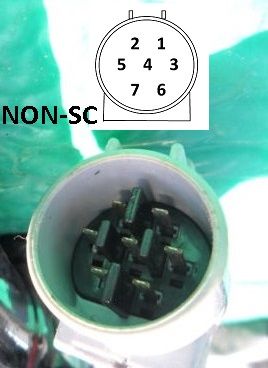
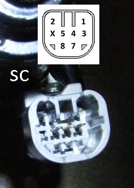
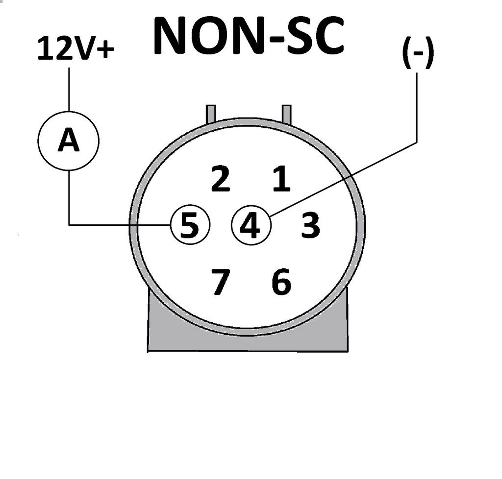
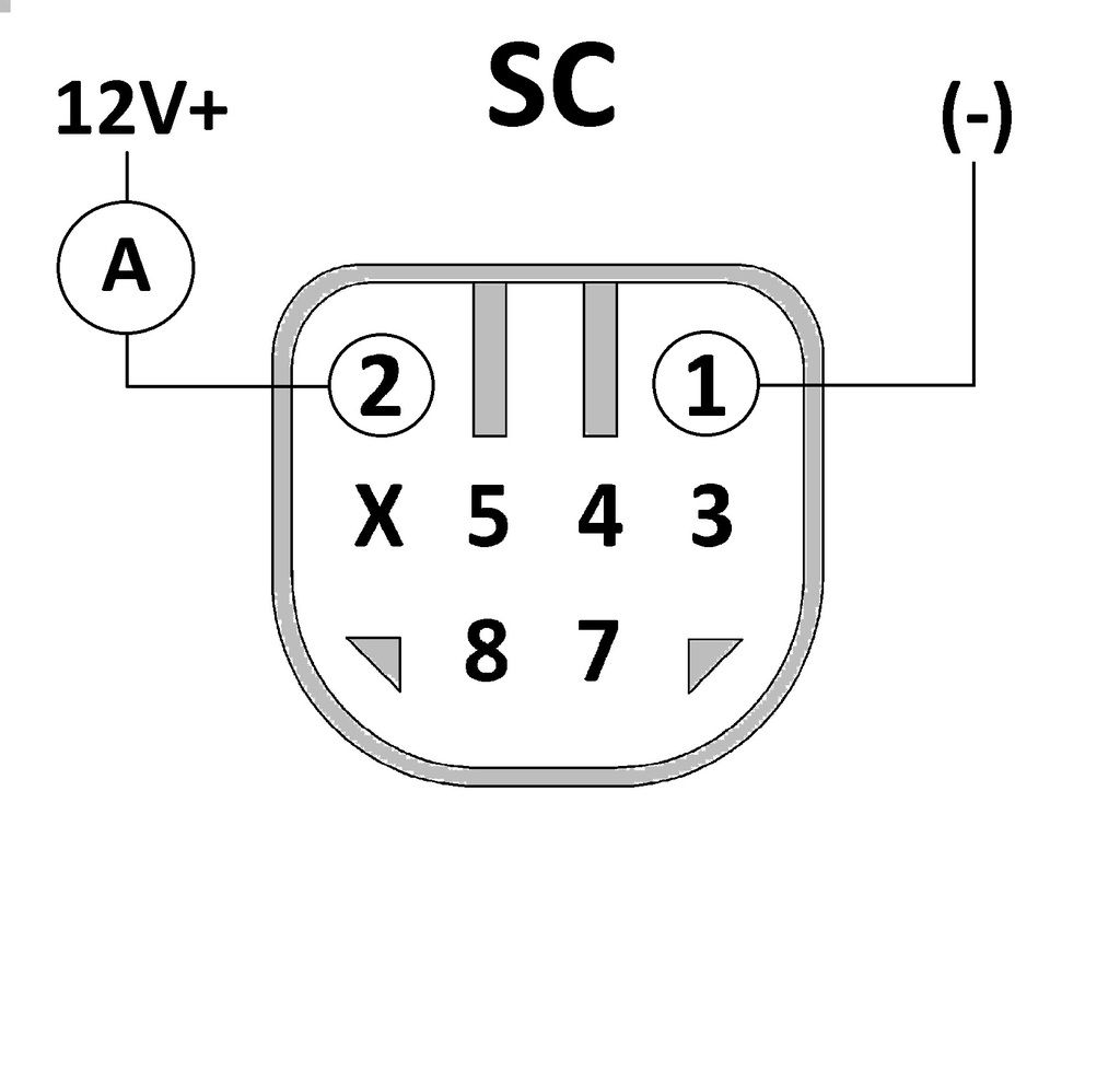
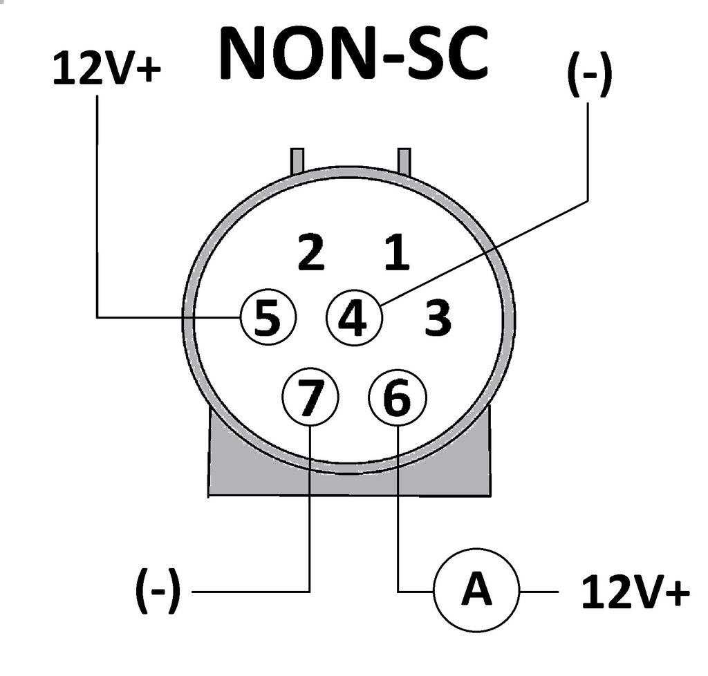
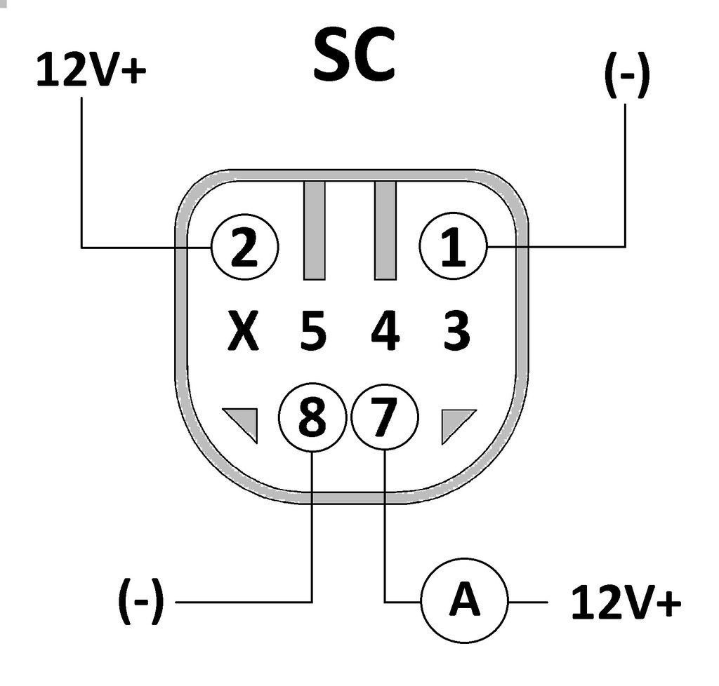
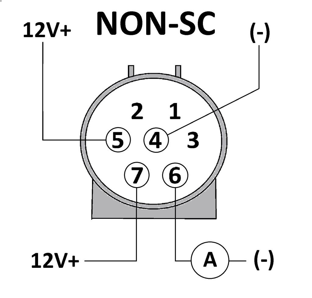
There are 7 pins in the connector for these seven wires. The NON-SC connector is a 7 pin connector with pins 1-7. The SC connector is an 8 pin connector with no pin in the #6 position.

If the Cruise was used heavily for its life, the brushes will probably go bad before anything else fails. It is a very tough and well-built actuator and so goes the price.

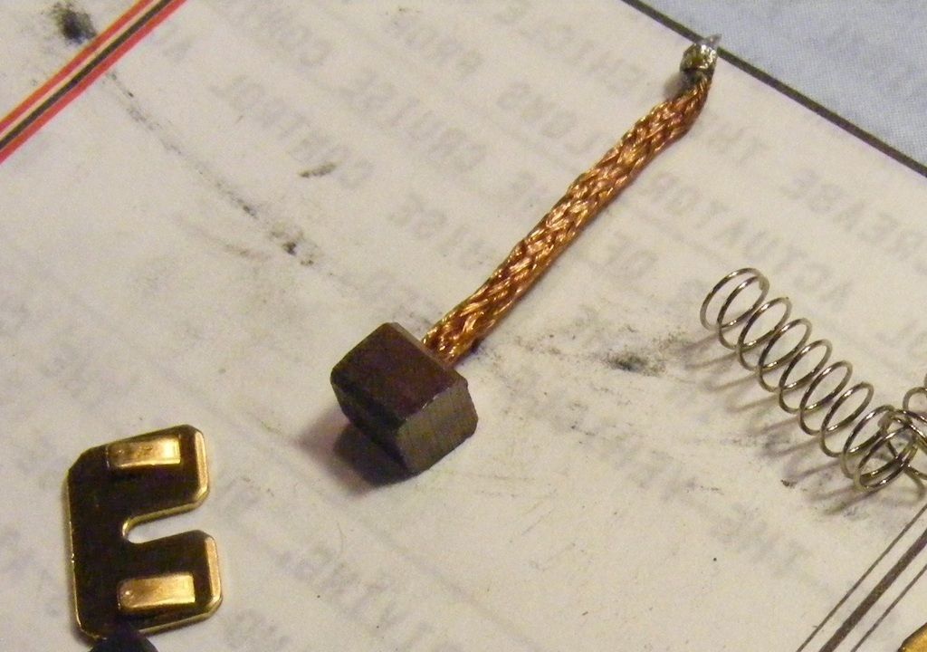
The brushes will eventually wear down to nubs. Their wear rate will be accelerated as load increases. (That’s why cleaning the goo out of the throttle cable is a good idea). Mileage is not necessarily a gage of how long they last. My 96 previa started giving problems at about 130k miles, probably because I use it a lot. But my 95 previa started to give problems at about 180k. I found and fixed the cable (Goo) problem below and that seemed to fix it until it started dropping out just now at 210k miles. Cable cleaning did not give me any reprieve with the 96 probably because the brushes were so far gone. Here is what a worn out brush from my 96 SC looks like.


1. READ THE PROBLEM CODES:
The code reading procedure is similar for the SC and the non-SC Previas. I recommend a fresh read of the codes. The CC ECU circuits were improved between the 91 and the later SC Previas. With the 91, problem codes were only retained in the ECU as long as the ignition remained on. Once the ignition is turned off, the problem codes are lost. With the SC Previas, the problem codes are retained in the CC ECU with ignition off and are cleared by pulling the ECU-B fuse for 10 or more seconds with the ignition off. I do not know if the procedure changed with the later NON-SC Previas, but the important thing to note here is that the codes you will see if your brushes are bad will be the same for all models.

To get a fresh read of the codes, the car must be drivable.

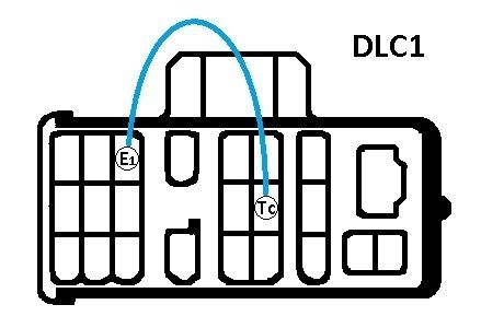
For the SC Previas, reset the codes with the ignition off by pulling the ECU-B fuse for 10 seconds with the ignition off, then drive the car and use the Cruise until it drops out. You can stop the car and read the codes then or shut it down and do it later. To read the codes, turn the ignition on and with a piece of wire, connect E1 and Tc in the DLC1 connector under the driver seat (see drawing). The problem codes will then flash out on the Cruise lamp in the instrument cluster.


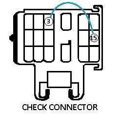
For the 91 Previas,(and maybe the rest of the NON-SC Previas, check your shop manual), drive the car and use the Cruise until it drops out. Bring the car to a stop, but don’t turn off the ignition. To read the codes, use a piece of wire the same as for the SC Previas and connect the same two terminals in the connector under the driver seat (see drawing). The pin arrangement is almost identical but the connector is called the “check connector” instead of the DLC1. The pins are in the same place and are called pins 3 and 15 instead of E1 and Tc. The problem codes will then flash out on the Cruise lamp in the instrument cluster the same as for the SC Previas.


If everything is normal (no problem codes) you get continuous short flashes (about 2/second)
If you have problem codes, then as long as the ignition remains on and the jumper in, all codes will read out from lowest to highest and repeat over and over. (example 11,13, ___ 11, 13, ___11, 13,___...and so on)
All codes are 2 digits
All the possible codes in my 95 and 96 manuals are the same (11, 12, 13, 21, 23, 32, 34, and 41). The codes for the 91 are almost the same (11, 12, 13, 21, 23, 31, 33, and 41), but the same codes (11 and 13) are likely to read out for worn out brushes. Each code means something different and you may have any number of codes read out.
Timing of the flashes will be like this (if this doesn’t make sense to you, maybe the examples below will):
Jumper wire connected, (4 sec wait), FIRST CODE, (2.5 sec wait), SECOND CODE, (2.5 sec wait), THIRD CODE…until all codes are read then repeat. There will be 1.5 seconds between the two digits in a CODE, the number of flashes for each digit will come at a rate of 1 per second and each flash is about 0.5 seconds long
Example of what codes 11 and 13 will look like (Below, each character represents 0.5 seconds, “-“ means cruise lamp is off and “0” means lamp is on):
Connect the jumper
--------0---0-----0---0-0-0--------0---0-----0---0-0-0--------0---0-----0---0-0-0 and so on
This is interpreted as:
______1__1___1__3_________1__1___1__3_________1__1___1__3__

Another example for code 41 (cruise ECU malfunction):
--------0-0-0-0---0--------0-0-0-0---0--------0-0-0-0---0 and so on
Interpreted as:
_________4____1________4____1________4____1_

Another example of codes 32 and 34
--------0-0-0---0-0--------0-0-0---0-0-0-0--------0-0-0---0-0--------0-0-0---0-0-0-0 and so on
Interpreted as:
________3____2________3______4__________3____2________3______4__

My 96 output the first example above, codes 11 (excessive current flowed to motor drive circuit) and 13 (Position sensor circuit abnormal or Open circuit in motor). If you get either one of these, I would next pull the actuator for a bench test.
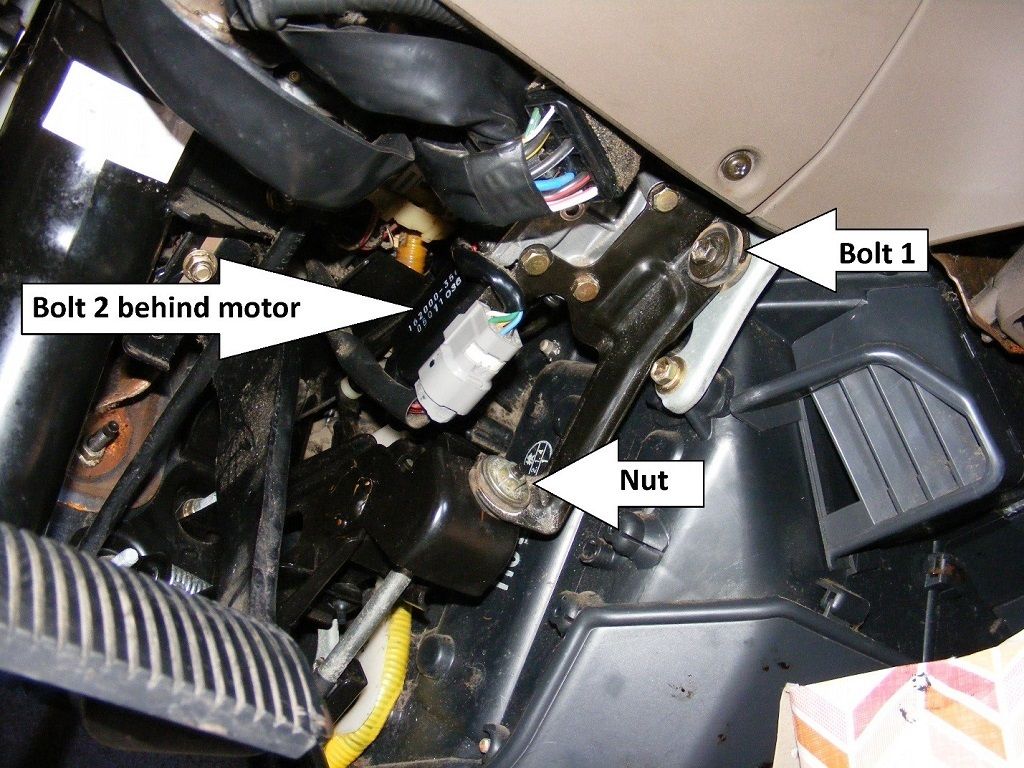
2. REMOVE ACTUATOR
The actuator is held in by two identical bolts and one nut and is pretty easy to remove. I don’t find it necessary to disconnect the battery, but you can do so if you like.
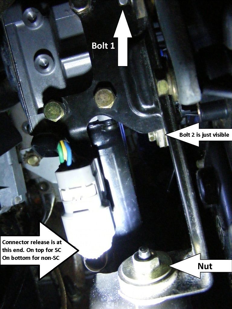
Unplug the electrical connector. The connector release squeeze part is on the wire harness side on the top of the wiring harness connector (motor side) for the SC and on the bottom of the connector for the NON-SC Previas. I also try to show the connector release location two pictures down.


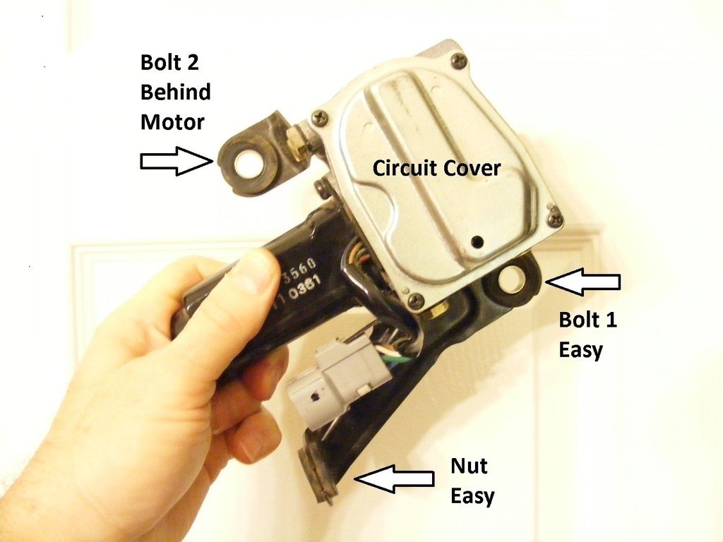
Reach bolt 2 with an extension of the right size (I seem to remember 2-3 inches) and ¼” drive. Maybe play around with a deep socket as well.


Once connector, bolts and nut are out, you can lift the cruise off of the nut’s stud and it will drop down. Gently rotate it, while not binding the link rod and ball socket, to the position shown.


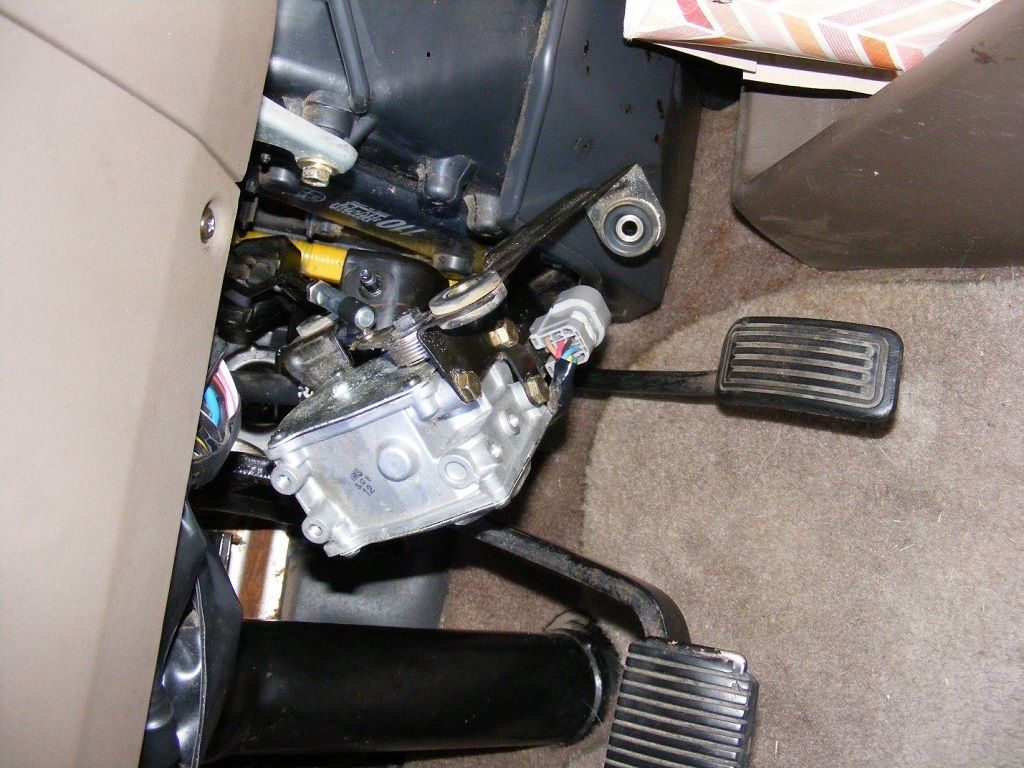
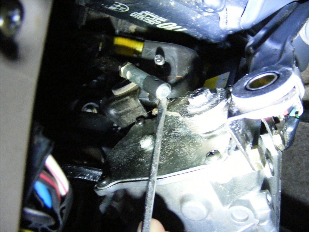
Using a small screw driver, pry the link rod off the ball. The spring clip on the link rod will let the ball free with fairly light force, so don’t force it if you are not on it right. Pry between the link rod end and the lever arm, as I tried to show here on my back with a camera and flashlight in my face.


Once it pops off, the actuator drops in your hand. Now take it to your electrical bench (or kitchen table).
One word of warning, the link cable is now just dangling. I would not and did not drive the car like this. I just left it until I had repaired and reinstalled the actuator. If you need to drive while the actuator is out, you should probably unhook the link rod from the other end and remove it so it can’t bind up your accelerator.

3. CLEAN CABLE
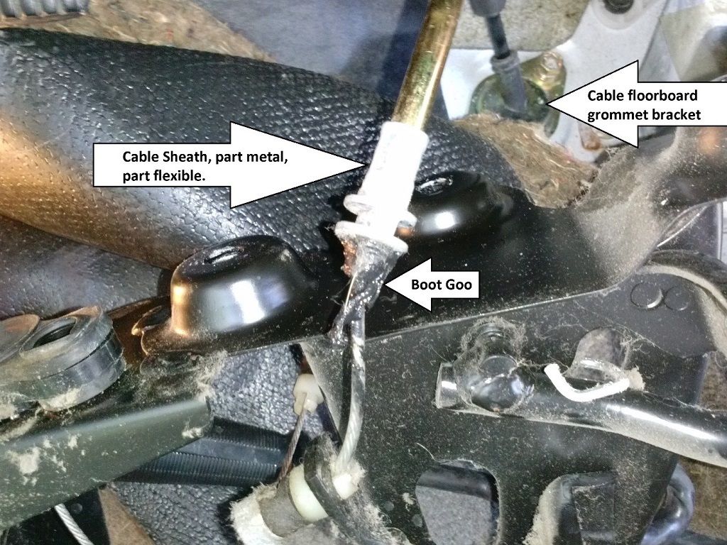
This can be done easiest anytime while the actuator is out Your arrangement may be different for NON-SC.I inspected all three cables in my SC. I only found a problem with the cable that goes from the accelerator pedal thru the floor board to the intake manifold block under the driver seat. This goo in the picture was once a small rubber dust boot where the cable comes out of the sheath. It has turned to goo on both my 95 and 96 previas and been pulled into the cable by cable motion. It adds drag to the accelerator movement. While you may not notice it much with your foot, it is significant to the cruise actuator. To clean it you must remove this cable from the car, which is not too hard.


Removing your cable may be a little different on NON-SC Previas.
I removed the accelerator pedal bracket which you see in this picture because I was inspecting everything, but you may be able to pull this cable out without doing that. Peel back the carpet (there is Velcro behind the steering column) to reveal the floorboard grommet bracket. In my 96 Previa, I also had to remove the floor console to get access and free up the carpet (more Velcro). The floor console was not in my 91 Previa. Remove the two bolts holding the cable floor bracket grommet and unclip the cable from a spring clip under the car. Unhook and unbolt the intake block end of the cable. I marked the position of the set nut on that cable end so I could put it back where it was.later. Unhook it from the accelerator pedal bracket and pull it out from inside the car. Once out, the only solvent I found that would cut the goo without damaging the cable is lacquer thinner. Put on some nitrile medical gloves. Apply lacquer thinner to the cable, move it in and out a bunch of times and try to work the lacquer thinner into the cable to dissolve the goo. Wipe the softened goo off the cable, and repeat until you are happy with it. I’m guessing I did it more than 20 times. Several times I used compressed air at the other end to try to blow anything I could out of the cable. I then applied a light plastic-compatible grease to the cable and worked it in. Then reinstalled it. With NO BOOT this time.

4. BENCH TEST ACTUATOR
First just move the ouput lever arm stop to stop. It should move freely and when released, snap back to the idle end (DOWN Stop).
The SC and NON-SC connectors are shaped different. The pin assignments are different as well. The NON-SC connectors have pins numbered 1 thru 7. The SC connector is an 8 pin connector with no pin in position 6.
Warning: There are some errors in the Toyota schematics and shop manuals with respect to the cruise actuator. I will cover this in a separate post. My 1995 and 1996 Toyota shop manuals call for testing the wrong pins. Testing with battery power as instructed must have the correct pin outs or things can fry! There are also errors in the 1995 and 1996 electrical diagram manuals. So my advice is to be very cautious.
If you are curious or want to trace wires yourself, or want to test and inspect the limit switches or diodes directly, you can pull the electrical cover from the side of the actuator. Nothing will fly out at you. It is a vented panel held with 4 screws and not sealed. However, I would not pull the lever arm panel on the other side as things could spring out at you. Besides, If anything is bad in that side of the actuator, then I would consider the actuator a loss.

The SC Actuator connector pin arrangement for both types:
:

To help understand the actuator’s operation and the values that you will measure, I felt that a better schematic than appears in the Toyota Electrical Schematic would be a good idea. This is how all actuators work, only the pin assignments are different. This schematic shows the correct pin assignments for both types of actuators and illustrates the correct position of the limit switches for the actuator in the off state (which is normally the convention of the Toyota electrical schematics). In the off state (lever released, throttle down),the position sensor is also shown in the schematic as linked to the limit switches and at a relative resistance value indicative of the actual state of the actuator at rest in the car or on the work bench. So the behavior and resistance values measure will make sense, unlike the schematics in the Toyota manuals.


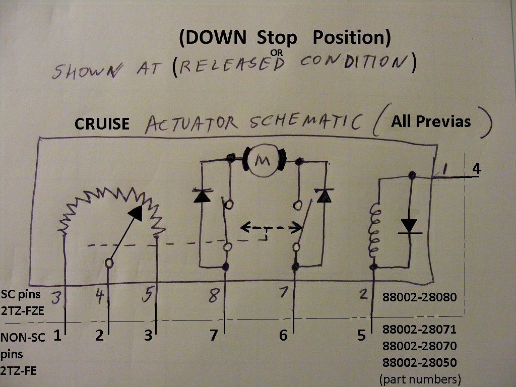
To check the three circuits of the actuator for any obvious failures,, set your ohm meter to the 200 ohms scale.

CLUTCH SOLENOID:
SC: pin 2 to pin 1.
NON-SC: pin 5 to pin 4
Should be aroung 40 ohms. (Book says 39.5, I get 40 and 40.5)

POSITION SENSOR:
Set your ohm meter to the 20 k ohm scale.
SC: pin 3 to pin 5.
NON-SC: pin 1 to pin 3
These are the potentiometer end connections. With the lever arm at throttle down stop (released) Should be around 0.200 kohms (book says 2 kohm. I get 1.960 kohm at room temperature

Set your ohm meter to the 2k ohm scale.
SC: pin 4 to pin 5
NON-SC: pin 2 to pin 3
(pin 4 is the potentiometer wiper connection) with lever arm released, should be around 0.500 kohms. (The book implies about 0.500, I get 0.510 at room temp)

Now test the position sensor center tap contact for wear by continuing to measure the same pins (4 to 5 or 2 to 3 as before) while slowly and smoothly moving the lever arm from one stop to the other and back. The reading should also rise smoothly to around 1.700 kohm and back down smoothly as well without glitching off scale high. (potentiometers sometimes wear out and get “noisy” like the old volume controls in radios). Mine had no problems, but check this anyway serveral times and make sure you have good solid connections to the pins so you don’t get a false reading. Glitching will send erroneous position data to the Cruise ECU. The actual readings are not that critical so expect the bottom resistance to be around 0.500 kohms and the top number to be 1.600 to 1.900 kohms (The book says 0.500 rising to 1.700, mine goes 0.510 to 1.780) The important thing here is no glitching.

MOTOR:
Set the meter to the diode test setting (usually one of the resistance scales has a little diode symbol on it, typically the 2k scale). Polarity here is important or you may not get a proper reading. Testing here may give different readings depending on which scale you use on your ohm meter and which pin the positive lead is on.
SC:positive red lead on pin 7 and negative black lead on pin 8.
NON-SC: Positive red lead on pin 6 and negative black lead on pin 7
You should get a reading of around 0.900 with the lever arm released. This means that the limit switches are in the proper positions, the motor has continuity thru the brushes, and the diode between the motor and pin 7 is good. What you are reading is the breakdown voltage of that diode with a circuit thru the motor and the “UP” Stop limit switch. That is a silicon diode and will conduct at voltage of around 0.6 to 0.8 volts. The function of the diodes is to conduct power to the motor in one direction only when the lever arm is at one of the stops (one for UP Stop and one for DOWN Stop). The function of the limit switches is to open the circuit and shut off the motor just before it reaches its mechanical limit (stop).
Now move the lever arm off the DOWN Stop to anywhere in mid travel. The resistance should go down to near zero around 0.02 k ohm or less as the DOWN Stop limit switch closes, bypassing the diode. This is the resistance of the motor windings and the two limit switches (mine reads about 0.017 or about 17 ohms on the 2k scale. Continue to move the lever to the UP Stop. The resistance should go off scale high as the UP Stop limit switch opens. If it does, that switch is working perfectly. Complete the test of the motor circuit by reversing the leads.
SC:positive red lead on pin 8 and negative black lead on pin 7.
NON-SC: Positive red lead on pin 7 and negative black lead on pin 6
With the lever arm all the way to the UP Stop, the value should again be around 0.900 .
All good? This means the three electrical circuits of the Actuator are good. Move on.

POWER ON TESTS
Continue here only if all tested good with the above tests.
This will test with 12 volt DC power. Using a current limited power supply is safer than using a battery. So if you use a battery be careful not to touch any wrong pins or create a short circuit. Using a 5 amp fuse in one of the battery leads will provide some protection.

You will need a 12v DC power source capable of a couple of amps. If you use a regulated power supply, set the current limit to 2 amps. You can get by with as little as 1 amp. A battery will do, but just remember that an unfused car battery can deliver vaporizing currents to a short or the wrong lead. I made up some test wires with crimp-on type female blade connetors that were small enough and the right size to fit snugly on the pins in the actuator connector. Whatever you use (needles thru the wirs, etc.), just get a good connection that won’t slip off or short something out. I used card stock taped between connector pins to make sure they would not touch each other inside the connector. The best way to test is to make solid connections in the connector, then connect the battery last to do each test.

MAGNETIC CLUTCH TEST:
To test magnetic clutch operation:
SC: 12v positive (red) lead to pin 2 and the negative to pin 1
NON-SC: 12v positive (red) lead to pin 5 and the negative to pin 4
WARNING: connecting backwards may fry the arc suppression diode that is in parallel with this coil.


With power to the magnetic clutch, try to move the Ouput lever arm. It should lock up. The output arm is now engaged with the motor drive train and only the motor will be able to move it. If you are measuring current, it will be about 300 mA (about the same as a typical automotive relay), but measuring it is not needed because the combination of correct resistance and verifying lockup proves it is working properly.

MOTOR TESTING:
I found it easiest to make up another two wires with narrow female connectors on them to hook up the motor. You can use the same battery to power the clutch and the motor, just use two sets of wires. That way you can leave the actuator hooked up and connect the other ends of the wires as needed to the power source without fumbling around in the tight connector and risking a short.If you have a current meter (use the 10A scale and connections), put it in series with the motor as shown. It is convenient to make the final connection at the battery with the current meter so you can glimpse the reading in the short time the motor is running. Also make it so you can change the polarity of the motor (NOT THE CLUTCH) so you can drive the motor back and forth. This test will drive the output lever stop to stop, back and forth. So do not have anything in the lever arm’s way or it will get broken.
Connect the battery to the clutch first as in the Magnetic Clutch Test above (you can leave this connected for hours. It will not hurt anything.
Then hook up the motor wires in the UP drive direction like this.
SC: 12v positive (red) lead to pin 7 and the negative to pin 8
NON-SC: 12v positive (red) lead to pin 6 and the negative to pin 7


When you connect the battery to the motor wires, the lever arm should quietly and smoothly move to the UP Stop at the end of travel in about a second or so. The motor will shut off when the UP Stop limit switch opens.
To drive the lever arm in the DOWN direction, with the clutch still powered, reverse the motor connections at the battery like this:
SC: 12v positive (red) lead to pin 8 and the negative to pin 7
NON-SC: 12v positive (red) lead to pin 7 and the negative to pin 6


The lever arm should smoothly and quietly move to the DOWN Stop position. If at any time you remove power from the clutch, the lever arm should snap back to its starting (DOWN Stop) position. The motor should be able to drive the lever arm only when the clutch is powered. So with the clutch hooked up, drive the lever arm back and forth by swapping the motor connections at the battery as many times as you want to get a feel for how it is operating. Note the highest current reading you can see on the Amp meter while the lever arm is moving. It should be around 0.300 to 0.400 A. The actuators that I have tested with good brushes would draw about 0.330 to 0.350 A You can also power the motor by itself without the clutch and it should free wheel inside the actuator without moving the lever arm. Just hook up the motor in the UP drive direction. It should hum quietly as long as it is powered. One word of CAUTION: When driven like this, the motor will dissipate about 4 watts of powere as long as it is hooked up. This is about the same amount of heat supplied by a 4 watt night light bulb. So I would not leave it on indefinitely, especially if it has worn out brushes. You can also hook up the motor power in the DOWN drive direction, but it will only come on if you also move the lever arm off its DOWN Stop to close the DOWN Stop limit switch. If current you measure is upwards of around 1 amp, the brushes are going. The actuator that I fixed was working some of the time and the motor was drawing about 1.7 amps in this test and was noisy with vibration. Just replacing the brushes fixed it. Good actuators I tested were all well below 1 amp, ran smoothly and were quiet.

Whew!!
I will post the fix next.
 
#7 · (Edited)
Cruise Actuator Toyota Shop Manual Errors, Need someone to test.

UPDATED 10-19-2015, I have completed my testing of a good 1991 Actuator and reviewed the 91, 95, and 96 Toyota manuals that I have for errors. This post is revised to list those errors.

I met with an old friend recently; my original 1991 Previa LE with only 130k miles on it. It has been off the road in a garage for about 7 years and is in surprisingly good condition. I was able to test its actuator and review the 1991 manual.
I was correct when I suspected that the 95 and 96 Toyota Previa shop manuals were not updated correctly. Part of the instructions, pictorials and wiring diagrams in the 95 and 96 Toyota shop manuals and electrical diagram manuals were for the earlier Previa actuators. The known errors are listed below. Since I do not have 1994 or 1997 manuals, I can only be certain about the 95 and 96 manual errors. However, I would recommend Caution and to look for similar errors when using those manuals as well.

Here are the problems with the Manuals’ accuracy that WILL confuse any effort to test these actuators, give incorrect test results, and may even turn otherwise good actuators into door stops by running power thru the sensor.

Error list:

1995 Toyota Previa Shop Manual RM409U,
Pg. BE-101 to BE-102; the Actuator pin assignments in the TROUBLESHOOTING flow charts for the ACTUATOR CIRCUIT are only applicable to 2TZ-FE (NON-SC) models.
Pg. BE-111 to BE-112; the Actuator pin assignments in the ACTUATOR INSPECTION are only applicable to 2TZ-FE (NON-SC) models.
For cross reference information on the proper pins to use in these tests for the SC models, see the Cruise Actuator Schematic and procedures in my post Cruise Actuator Fix Part 1.

1995 Toyota Previa Electrical Wiring Diagram Manual EWD208U,
PG 186; C17 connector is shown as round instead of the shape it actually is.
Pg. 183 and 189; the cruise control actuator schematics are shown in the FULL THROTTLE position (limit switch positions are reversed), not in the “ground”, “relaxed”, or “off” state as is convention. Measurements taken or operation may not make sense with this schematic.
Pg. 187; Pin callouts for cruise actuator may be incorrect in the explanation of Set Speed Control.
Pg. 191; C17 connector may have incorrect pin assignments

1996 Toyota Previa Shop Manual RM448U,
Pg. BE-87 to BE-88; the Actuator pin assignments in the TROUBLESHOOTING flow charts for the ACTUATOR CIRCUIT are incorrect.
Pg. BE-97 to BE-98; the Actuator pin assignments in the ACTUATOR INSPECTION are incorrect.
For cross reference information on the proper pins to use in these tests, see the Cruise Actuator Schematic and procedures in my post Cruise Actuator Fix Part 1.

1996 Toyota Previa Electrical Wiring Diagram Manual EWD242U
Pg. 143; the cruise control actuator schematic is shown in the FULL THROTTLE position (limit switch positions are reversed), not in the “ground”, “relaxed”, or “off” state as is convention. Measurements taken or operation may not make sense with this schematic.
 
#8 · (Edited)
wow, thanks for all that! I didn't even try to digest it all now but I'll be taking a look at my actuator issues sometime in the next few months and this will be very helpful I'm sure. I don't recall mine "cluncking" when it goes out though...on all my Previas it has clunked when I tap the brakes to disengage the cruise though, much more so than any other vehicle I've owned or driven. I wonder if this is a Previa thing, or whether it's just another indicator of the actuator problem that all my Previas have had? Does anyone else have a clunk when they disengage cruise with the brake?
 
#9 · (Edited)
Cruise Actuator Fix Part 2

This part 2 is a continuation of the Actuator Fix. Part 1 determined if the actuator likely has bad brushes. This part fixes it.

If you get to this point, the assumption is you are sure that the only thing wrong with the actuator is the brushes because a power on test showed the motor runs rough, noisy and with higher current than it is supposed to. The only parts I bought, modified and added to the actuator to fix it were the two brushes.

Proceed with this fix only after reading it thru first, and proceed by your own judgement and at your own risk. I assume no responsibility for any personal injury or damage to your car resulting from performing this fix. I welcome any comments and will incorporate improvements as appropriate.

This procedure should be identical for all Previa Actuators, as I have tested actuators for 91, 95 and 96 Previas. The brushes are easy to get to, but replacing them is a little intricate. However, it should be no problem for any typical model airplane or train enthusiasts. I did not unscrew anything but the two screws that hold the motor casing on and this provides access to the brushes for replacement. The work is fine so small fingers and magnifying glasses are a plus, especially for my age class. Read this whole thing before you decide whether you can do it or not.
You need a clean place to work where you can find a small spring if you let one get away from you as I did….twice!


5. REPAIR ACTUATOR
Remove the 2 screws that hold the motor case to the actuator housing. Slowly pull the motor case upwards. The motor armature will come with the case as there is no way to avoid it. You will see the brushes after lifting the case an inch or so. Try to avoid catching the brushes on any part of the motor shaft as you lift it out. This is what the motor case looks like.


There are two strong permanent magnets bonded in the case that will “hold on” to the armature. As you slowly pull the motor case straight up, the brushes may snap down onto the middle bearing journal and get contaminated by grease. You are replacing them anyway so no problem.
I didn’t take a picture of this as my hands were full and I was concentrating on what might fly out at me. Nothing did, and I may take a picture of this to include here if I ever take one apart again.
Continue to pull straight up until the motor case and armature are separated from the housing, Set the two aside in a clean place. CAUTION: You want to keep any metal filings or small metal parts away from this pair. And you don’t want to bang the armature around in the cover very much. The ceramic magnets are very strong and brittle and pieces can be broken off. Any metal parts or magnet fragments may be attracted to the magnets, and if not removed, may get ground up in or jamb the motor armature. So I suggest you carefully remove the armature from the motor case and immediately bag them both separately to keep them clean. The armature looks like this with a bearing at each end and one in the middle between the worm gear and the commutator.


Turn the housing opening side down and shake the carbon brush dust off and out of the opening and brush plate. It helps to use a fine hair brush like a model paint brush or a lens duster brush and maybe some light air dusting. The housing and brush plate looked like this after I brushed away the carbon dust and removed the brush on the right.


Don’t clean away any of the excess grease from the housing or armature as you can use it later to lube the journals and gear just prior to assembly. The brushes are spring loaded from a small removable brass colored retainer plate on the left side of this remaining brush. Keep in mind that all of the brush plate is plastic so it can be accidentally broken or melted. Here is what the worn out brush, spring and retainer plate look like.


You may notice that the factory brush is worn uneven because the electrical braid was binding in the slot on the top, causing arcing, high current and poor motor performance. Mine were worn to about 0.186”- 0.188” at the longest point. The brushes I used to replace them were purchased from ACE Hardware for $4.40 each. They were not the right size and the braid was attached to the back of the brush instead of the top. But these were the smallest they had and I was anxious to see if new brushes would fix the problem. I would make more effort to get a better fit brush next time around.
Unsolder the brushes from the terminal posts, and gently remove the retainer plate. CAUTION: When the retainer plate comes up, the spring will shoot out and find its way to a great hiding place unless you are ready for it. Also, the brush housing that holds the retainer plate is plastic and looks delicate. In this next step pry very carefully to only get the retainer plate up and not break the brush housing. Note the two lock tabs on the retainer plate in the picture above. These need to be moved past the lock recesses in the brush housing to get the plate up and out. I used a sharp object to gently pry up the retainer plate as shown here. In retrospect, tweezers would have been better than the pliers to hold the plate. This picture was taken just before the spring was released and flew out the back to find its hiding place.


This picture was taken as I am saying “wasn’t there a spring in there?”


You can also unsolder the brush at this point if you didn’t do it earlier.
Here is that brush removed next to the larger brush I bought to replace it.


If anyone has a better source for a better fitting brush, they should post it and save everyone some of the custom shaping I did with a sheet of 320 grit sand paper. The paper grid above is 0.250” x 0.250”. The cross section of the factory brush is 0.154” x 0.154”. The brushes were worn crooked as the braid hung up the top side. Notice the new brush has the braid attached to its end inside the spring. I cut the braid at the retainer on the other end and discarded the spring. I sanded the new brushes very carefully to keep them as square as I could and bring them down to around 0.157” square, but they were not perfect. I cut the contact end to length while shaping it roughly to the commutator curve in a later step. I routed the braid thru the original spring and retainer with no modifications. The braid was just long enough.

Here is how I hand sanded the new brushes to about the right size. I am holding the shaped brush above the sand paper I used to slowly grind it down to the right dimensions. The sand paper is wet/dry 320grit. I wore thin nitrile gloves to avoid getting skin oils on the brushes. The carbon dust is just black and easily washed off, not a hazard to my fingers. The brushes sand very easily so you need to take care to avoid sanding at an angle. Work slowly and make a lot of measurements to keep from sanding too much, or in the wrong place, or at the wrong angle.


Here is what the shaped brushes looked like compared to one of the old brushes. At this point the new brushes are too long and need to be cut to the proper length next.


Another view of an old worn brush still in the brush housing on the left and my shaped new brush on the right being checked for fit prior to cutting to length. Notice the old brush braid wire comes out the top and the new brush braid goes out the back of the brush housing. Either will work with no modifications to the spring, housing or retainer plate.


My goal was to put the longest brush that I could fit in the reassembled motor. To do this, I measured the diameter of the commutator and found that there was very little clearance between the brush housing on both sides and the commutator. I reasoned that I needed to mock up the spring, plate and brush and mark a cut line on the brush just outside the brush housing with the spring fully compressed. Here is the new brush with the spring and retainer in place (retainer not locked down), with me pushing on the brush to fully compress the spring. I have drawn a white line on this picture where I gently scribed a line with a needle on the brush. I used the curve of the brush housing as a guide for the needle and this was my cut line. Notice it is curved to approximate the curvature of the commutator. Matching the curve exactly is not necessary as the brushes will wear in themselves. Approximating the curve just makes the wear in process shorter.


I then removed the brushes and cut and shaped the end with a rotary tool. It was very rough but worked fine. I suppose I could have done the final shaping better with fine sandpaper on a rod of approximately the right diameter, but didn’t take the time. I put the springs on each brush braid and inserted the braid, spring and brush partially into the brush housing from the commutator side. I then snapped the retainer plate in place with the braid going freely thru it. Make sure the lock tabs on the retainer plates hold them in place so they will not slide up. I then soldered the braids to the terminals. Careful not to solder too long on the braid or it may become rigid too far from the terminal. I had just enough braid to allow the brushes to move freely in and out. The Braid also cannot be too long or it may short-out on the motor case once installed.
This is what the new brushes looked like just before I installed the armature.


I now made the armature ready to install by cleaning the commutator with some isopropyl alcohol, and moved some of the grease around. I took a small amount of the grease that seemed to be sidelined on the ends of the worm gear and spread it onto the three bearing journals and put some in the middle of the worm gear. See pictures. I also spread some around the gear inside the actuator housing that the worm gear meshed with. It turns freely. Just don’t drop any junk into this hole by accident. It may be hard to get out. My objective here was to re-lube the motor while keeping everything clean.


To reassemble the motor, you must use some tricks to put the armature and cover in place. To place the armature, you need to protect the brushes from getting broken or getting grease on them. I cut up a card and put it over the brushes as shown in the picture. Slide the armature straight down into the housing to this point. Then gently and slowly shimmy it down while alternately pushing the brushes into the brush housings. Once the brushes are on the commutator, you can pull the card out.


Once down, it looks like this. The commutator is very close to the brush housings. The brush springs should be nearly fully compressed, but not binding, if you cut the brushes to the proper length.


Now the tricky part. Sorry, I don’t have a picture. You are going to replace the motor cover in the same orientation that it came off. Mine has the Toyota part number label on the lever arm side. And remember, don’t force anything. If you can’t shimmy it into place gently, then something may be wrong. Assuming the motor cover is still sitting in that bag, clean and pristine, remove it and make sure there is no debris in the cover or stuck to the magnets. The trick to installing it is to hold the armature down into the housing while you gently slide the cover down in place over the armature. Sounds easy but the strong magnets in the motor cover can and will pull the armature out of place before you get the cover half the way down. If the armature is pulled up, the brushes may snap down off of the commutator and onto the greased middle armature bearing and get contaminated. Forcing the armature and cover back down in this condition will break the brushes. To keep this from happening, the trick is to wrap a strong plastic fishing string or something like that around the “waist” of the armature like a necklace around the neck, one loop around. Then hold the two string ends firmly down on the lever arm side of the actuator. The “waist” of the armature is the narrow wired part between the commutator and the armature core windings. The string I used was a very strong and abrasion resistant synthetic thread used to sew patio furniture fabric. I used the lever arm ball as a tie point for the strings like a hitching post. Firmly hold the armature down with this string while the motor cover is shimmied down almost all the way (within about a quarter of an inch of closure). Then the string can be loosened and pulled out, and the motor cover moved the rest of the way down. When you loosen the string, the armature may move up slightly, but the brushes should still stay on the commutator and the cover and armature together can be slid down to closure. The string or line needs to be pretty strong and held firmly under tension while the cover is installed. Once the cover is on and the two screws replaced, you can test the motor in free wheel mode as in PART 1 to see that it runs smoothly. My motor ran smoothly right away, but not as quiet as a new motor, and the current was a little over 1 amp. But after testing it for a few minutes, it gradually got quieter and the current continued to drop as the brushes wore in.

6. REINSTALL, CLEAR CODES AND ROAD TEST
By the time I installed it in the car, the current draw was down below 700 mA and still falling. Installation is the reverse of removal. The first step is to place it under the dash in the position shown in part 1 where the link rod was removed. Make sure there is at least a minimal amount of grease in the ball socket or on the ball. Just snap the link rod back down on the lever arm ball. Rotate the actuator gently to mount the lower bracket hole on the nut stud, then replace the two bolts and the nut. I squished a little bulb grease (dielectric grease) into the contacts face of the wire harness connector (as I do with all my electrical connections) and snapped it back on. Clear any codes if yours is an SC by removing the ECU-B fuse for 10 seconds and hit the road for a test. Mine has worked flawlessly now for a couple of trips and months.
 
#10 ·
Hey, I just want to say thanks. This is a heck of a write up. I'm adding factory cruise control to a 95 Geo Prizm (corolla). I got all of the parts from the Cleveland Pull-a-part, used for just under 100 bucks. After the install I'm getting similar symptoms. The cruise control light lights up when the system is activated just like it should. But when I try to engage the system, it barely pulls the pedal, and on a rare occasion may run for 10 seconds or so before it noticeably gives up and the light starts blinking then goes out. Of course I thought that this was because of my wiring job, I DID build it from scratch after all. But after this wonderful post I investigated the actuator as instructed and found my brushes to be worn out as well. So tomorrow I head back to Cleveland to exchange for another actuator. Luckily I saw two more ready to be pulled when I was there a few days ago. I plan on replacing and testing while I'm there. (Its a 4 round trip after all.) If I cant find a working actuator I may attempt the rebuild above. I'll let you know how it goes either way.

It should be added that my actuator (while having different brackets) is VERY similar, if not exactly the same. So everything above should work for 94-97 Corollas and Prizms. (and probably a lot of other Toyotas)

PS, I took a LOT of pics while adding factory cruise. I may just have to do a write up myself some day. Especially considering everywhere I went, everyone said it was too hard to accomplish.
 
#11 ·
Ok, so the wonderful conclusion to my story... I went back to Cleveland, pulled the two remaining actuators, took them apart in the junkyard to inspect the brushes and found both to be in pretty good shape. I tested them both on the way home. Both worked slightly better and longer than the original, but refused to work properly. So after several days testing the self built harness for continuity, voltage, and proper operation of the switches involved, I gave up and set upon installing the the toyota airbag. (i had to switch to a toyota steering wheel because my geo wheel wasnt set up for a cruise switch) So upon the install my airbag system warning light wouldnt go out. So i took to the internet to find out how to reset it. Turns out it was semi complicated and took some rhythm. When i screwed it up on the original try, my airbag light was blinking out a code. And it dawned on me, the airbag computer blinks its own codes in 95 because no OBDii yet. So then i thought, i wonder what happens when i ground the cruise pin... and sure enough, there was a code 13.

Soooo, that sent me back to the interwebs looking up the code. Which lead me to a 16 page 96 supra cruise control shop test. Which aside from different color wires and a few different pin locations was pretty much the same. (And also which you covered most of above, but there were a few things new) At any rate, the tests didnt help. My system was at perfect voltage, ohms, and amperage on every pin wire and switch. Yet refused to work. I even was able to hook up an amperage tester in the passenger seat for a road test it never pulled more than .7 amps to the motor.

So, as a last ditch effort, i ordered a used cruise control computer from ebay because its the only thing that haddnt been replaced. It came in the mail tonight and i didnt even want to try it because i was sure it wouldnt help and id be forced to give up. But i did anyways. And sure enough IT WORKS! I cannot believe it, but the original computer i pulled had been bad from the start. (has me wondering if the original actuator was good?)

At any rate, moral of the story, Do Not rule out the computer regardless of testing results.

Also, here is the link to the supra shop test. Keep in mind the wires and pins WILL be different unless youre working on a supra. But if you know what youre doing what what wires do what... you can use it as a huge troubleshooting guide. http://www.clubsuprafrance.com/Dossiers/revue techniquesupra/SUPRA_MKIV/CRUISE_CONTROL_SYSTEM.PDF

Thanks again drocketman
 
#12 ·
Cruise Control Actuator fixed.

Just thought I would update this thread with performance since the fix of my actuators almost 3 years and 41k miles ago.
Both actuators and cruise control systems are still operating great. Brush replacement fixed both actuators for the long term. I believe it also helped to clean and re-lubricate the throttle cables to lower the actuator load.
 
#14 ·
Yes, it looks like those 4mm sq cross section brushes are about right. That will save you some time and the brush should fit better than my hand shaped ones. I did not measure the final length. As explained in the text, and shown in the picture, once I had shaped the brush to the proper cross section, I fit checked it (with the spring and retainer clip in place) into the brush housing and pushed it until the spring was totally compressed. I then scribed a light mark on the side of the brush along the curve of the brush housing to use as the cut line of the brush. With the spring fully compressed, this condition approximates the longest the brushes can be. As you can see from the picture, a lot of the brush had to be cut away, but what you are left with is considerably longer than the worn out brush.
An added note here:
The braid attached to the end instead of the side of the brush will not make any difference in the operation of the motor during the useful life of the new brush. However the two configurations may have a different end-of-life behavior. The original side braid attachment served to hang up the brush on that side while the spring continued to push on its center. This pushed the brush crooked in the housing so the brush made progressively poorer contact with the commutator as it wore on. Once the new brush wears out, it will hang up by the braid in the center of the spring so that it will not be driven crooked. If the braid is not too long, it will just eventually prevent the brush from making contact as the brush wears and the braid becomes taught. Sadly, I may never know how long my brush fix would have lasted. Mine never wore out and was still operating perfectly in daily use when a 25mph deer collision ended my 236k mile run with our 95LESC. I stripped it of all easily removable parts which included my repaired cruise actuator. I am keeping all the spare parts for my 96 previa, if it ever needs them, or for some other interested party. I had also replaced the brushes in my 96 previa's actuator and it is still going. I had purchased a used actuator as well and so I am actuator rich at this time.
 
#16 ·
So happy to find this forum and this thread on Previa cruise control !! manuals and YouTube videos are lacking this is the most detail I've seen anywhere still reading through the details but a simple question... I have a 1991 previa le ( a virgin @118k ha ) and seems my cable for cruise control is either stuck or broke can you tell me where the cable attaches to the cruise control unit ? seems the cable end that goes to my throttle body will not retract and it is hard to trace this cable .any help / pics would be greatly appreciated,

thanks!
Image
 

Attachments