

As with many of my DIYs this one originated from having to do the work and deciding to document it along the way. It appears checking and adjusting timing is knowledge that's slowly fading away as modern cars do not have a need for mechanical adjustments of ignition timing. So I figured let's get this one documented as it's a very important and easy item to check for those of us who have the "gen 7.0" Corollas with OBD-1 and adjustable distributors. (The OBD-2 95.5 - 97 vehicles do not have adjustable distributors.)
Tools you need:
Word of caution:
Prep work:
![Image]()
Close-up:
![Image]()
![Image]()
(Yes I know, tiny ratchet for a big job. Should have pulled out the bigger one but this seemed to work.)
![Image]()
![Image]()
In this photo you can see the 10 degree mark painted (indicated by the arrow) and you can also see the groove having a tiny bit of paint (slightly above the 10 degree mark on the outer rim of the pulley).
![Image]()
![Image]()
Check timing:
![Image]()
Adjusting timing
![Image]()
![Image]()
Left bolt:
![Image]()
My extensions put together for the torque wrench:
![Image]()
To recap on the factory spec - it's 10 degrees BTDC. I drove around with mine at 15 degrees BTDC for the longest time and it seemed fine. Some claim that (especially in combination with higher octane gas) gives more power and MPG, but so far my butt dyno seems to like the 10 degree setting better in terms of torque.
Enjoy!
Tools you need:
- Timing light. I decided to splurge a bit and got an Innova 3568 light - it's very nice and easy to read, and also does RPM/tach. I suspect any cheapo light will work fine, but if the bulb is weak you might have to do this in a pretty dark setting to see properly.
- 17 mm, 12 mm sockets (6 sided preferred); a couple of extensions and a flexible joint; rachet; torque wrench appropriate for 15 ft/lbs torque
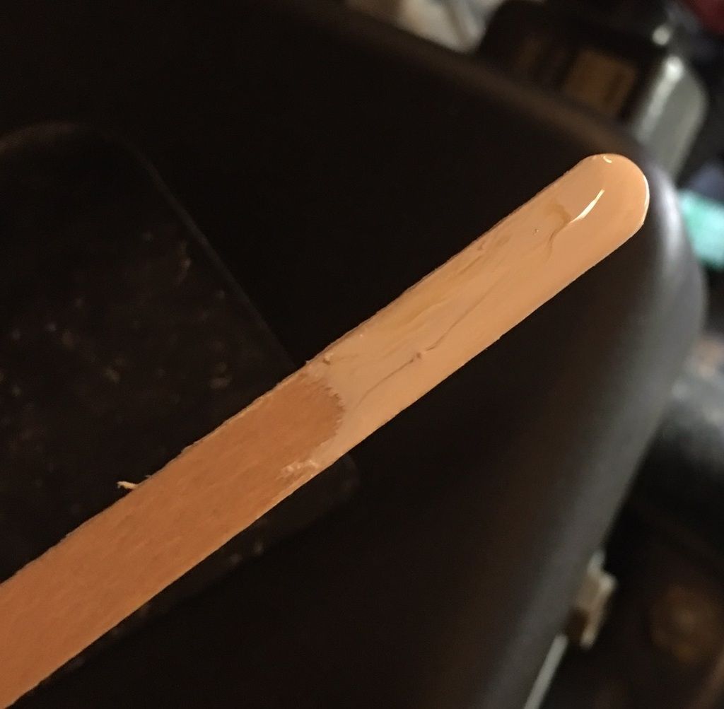
- A tiny bit of bright (I used white) paint and something to apply it with (I used a Starbucks coffee stirrer...). Use whatever you have on hand.
Word of caution:
- You are responsible for your own work, I am just documenting what worked for me. Work responsibly, and the biggest caution on this work is focused on the fact that you'll have to start your engine a lot and switch back and forth between having a running engine and working on that engine. Double check before starting the engine, e.g. stuff like REMOVE the ratchet you'll use on the crank pulley BEFORE starting the car. Don't be dumb.
Prep work:
- Before doing this, you MAY be lucky and have the crank pulley at top dead center (TDC) already. Use a flash light and look down the passenger side of the engine bay. The bottom pulley is the crank pulley (a.k.a. harmonic balancer). There's a slight notch in the pulley to indicate TDC. If you see this notch and can access it to fill it with a droplet of paint, you can skip through the next few steps.
- If you have a manual car you need to make sure the gear shifter is in neutral (hand brake applied, please!). If you have an automatic just leave it in P.
- Turn the steering wheel all the way to the right. Alternatively you'll need to jack the front passenger side up and remove that wheel but it's not needed as long as you just turn the wheel.
- Ignition OFF and keys OUT of the ignition. If you want to be extra sure you can disconnect the negative battery terminal.
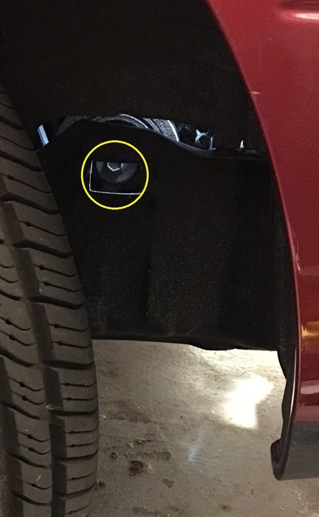
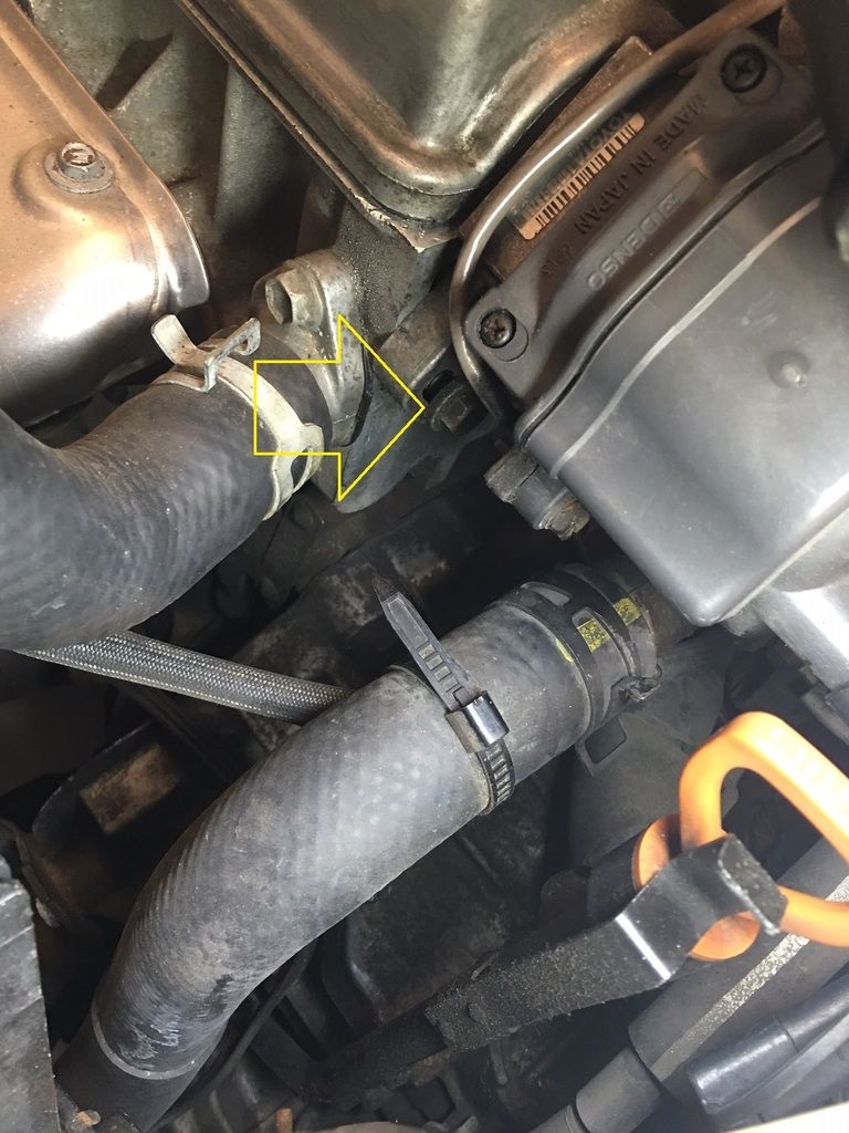
- Look in the front passenger side wheel well. You'll discover there's a cover that covers up the crank pulley bolt access. Pop that cover off - it should come off pretty easily. This is what you're looking at once it's off:
Close-up:
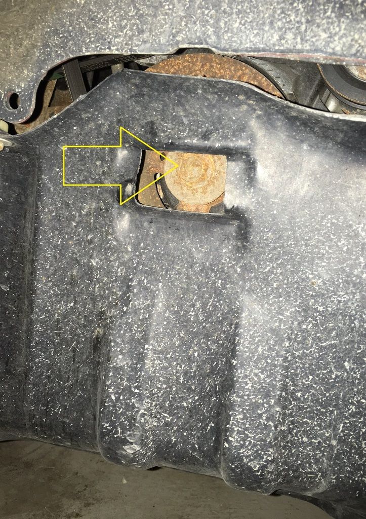
- Now, get your ratchet and extension and the 17 mm socket. Put it through the access hole and on the crank pulley bolt.
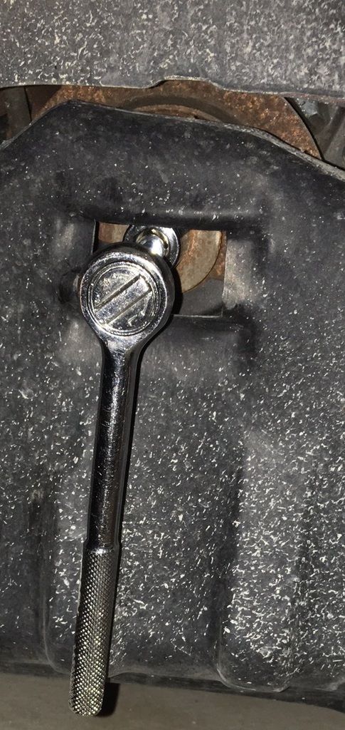
(Yes I know, tiny ratchet for a big job. Should have pulled out the bigger one but this seemed to work.)
- The pulley should only be turned clockwise. Use the ratchet and slowly turn the pulley clockwise. If it's too hard to pull you can make it easier by disconnecting the spark plug wires and loosening the spark plugs, but to be honest that should not be necessary. If you do, remember to torque them back to spec after.
- Alternate between slow turns and then inspecting the top looking for the notch in the pulley. Once you find it, find the best position for applying paint and stop turning. If you turn too far do NOT turn counter clockwise, but just complete another full turn.
- Get some paint out and apply to the notch. Also apply to the timing cover line that indicates the number "10" (which means 10 degrees before top dead center). Some photos to help:
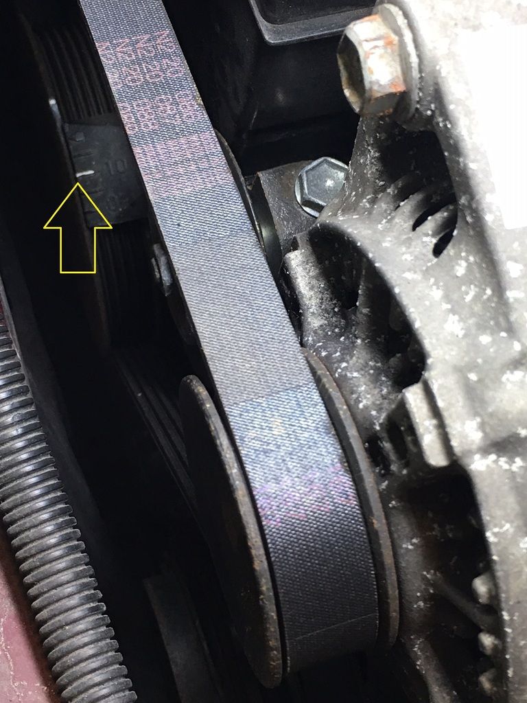
In this photo you can see the 10 degree mark painted (indicated by the arrow) and you can also see the groove having a tiny bit of paint (slightly above the 10 degree mark on the outer rim of the pulley).
- Let the paint briefly air dry as you don't want to sling it around wet.
- Remember to put the crank pulley cover back.
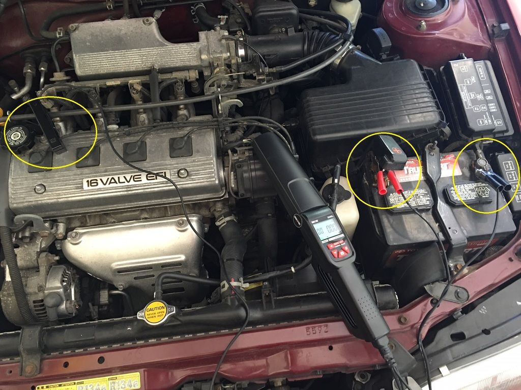
- While you're waiting for the paint instead of watching paint dry... be productive! Hook up the timing light. Whatever light you get should come with instructions but essentially you hook up three cables:
- Inductive pickup clip - clamps around the #1 spark plug cable (the passenger side one). Mine had an arrow indicating the direction vs. the spark plug.
- Positive battery cable (I like to always connect positive first)
- Negative battery cable
- Here's what mine looked like all hooked up:
- Start the car and let it warm up fully (if you prefer to do that before hooking up the timing light that's fine too).
- Once warmed up, turn the engine off.
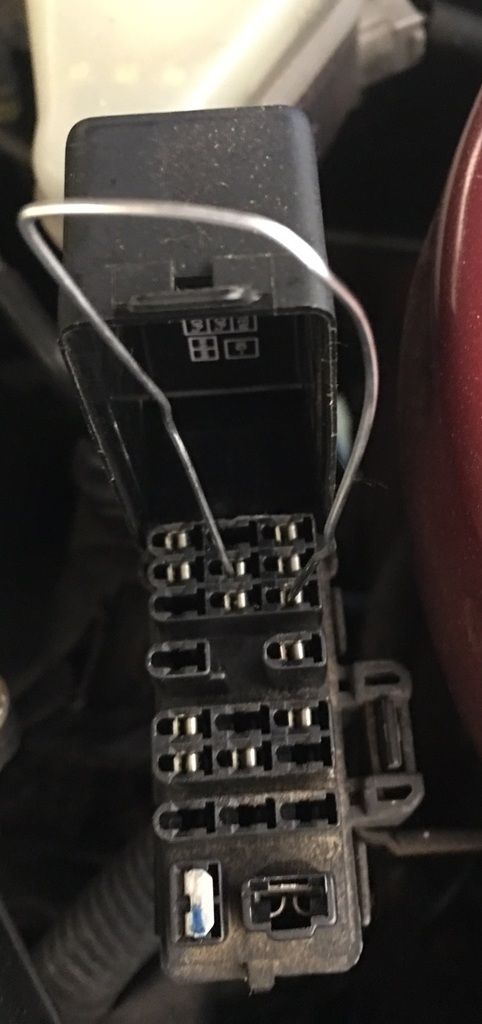
- Open the diagnostic tower on the driver side of the engine bay. You'll see the inside of the lid has terminal IDs. Connect TE1 and E1 like this - I used a paper clip:
Check timing:
- Start the engine again. TURN OFF ALL ACCESSORIES (AC, Radio, headlights, defoggers, etc). The idea is to have no accessory load on the alternator or the AC compressor.
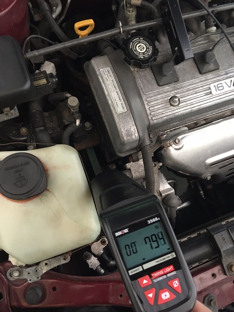
- Aim the timing light at the crank pulley area:
- If your timing is aligned according to spec the groove and the 10 degree mark should perfectly align when the timing light illuminates. If not, take note at how much retarded or advanced the groove is relative to the 10 degree mark (every line is 5 degrees).
- If everything aligns congrats - you're done! If not, keep going for the next section. Also you may want to check out how to adjust timing if you want to experiment with different settings.
Adjusting timing
- If timing needs to be adjusted you'll need access to the two bolts attaching the distributor. You'll need to remove the intake hose and air filter. It should look something like this when removed:
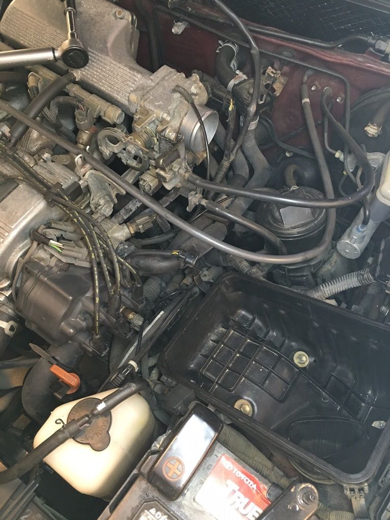
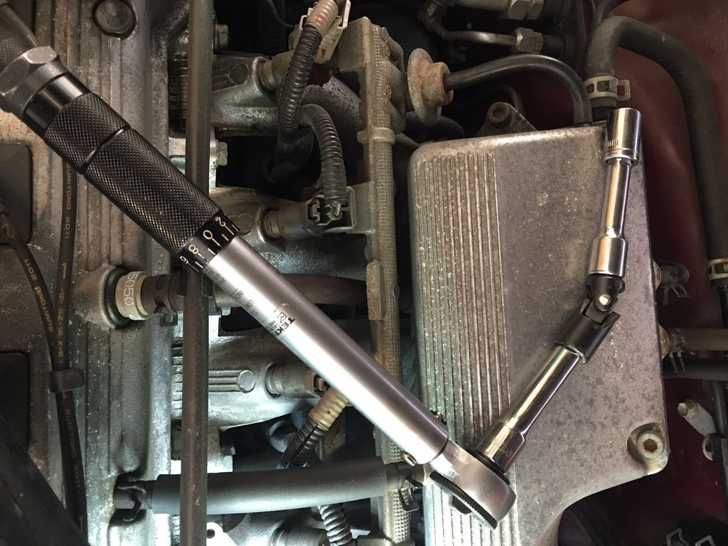
- The bolts are not easily accessible. I used a few extensions and joints to get there. Here are some pictures:
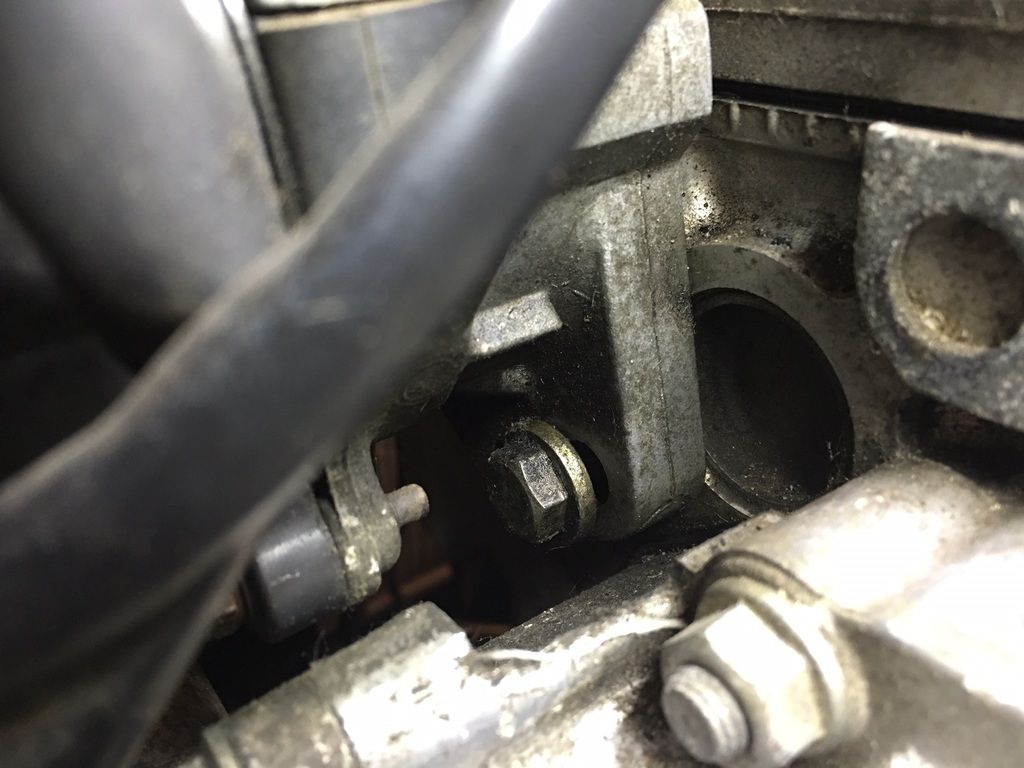
Left bolt:
My extensions put together for the torque wrench:
- Loosen both 12 mm bolts. To further advance timing, rotate clockwise. To retard timing, rotate counter clockwise. Note that you only need to move a tiny bit to shift even as much as 5 degrees. So do this in small adjustments and retest.
- Slightly tighten the left bolt for retesting. Refer to previous section to check timing.
- Once you have obtained desired timing, tighten both bolts with a torque wrench to 15 ft/lbs.
To recap on the factory spec - it's 10 degrees BTDC. I drove around with mine at 15 degrees BTDC for the longest time and it seemed fine. Some claim that (especially in combination with higher octane gas) gives more power and MPG, but so far my butt dyno seems to like the 10 degree setting better in terms of torque.
Enjoy!