We can really use your support right now. We are working on my cousins truck. It is a 1990 Toyota Pickup with a 22RC motor. We can't get the engine started. Previous to this problem the EFI relay was over heating. We feel that the after market alarm system that was installed was shorting out everything so we removed the entire alarm system. However, by then we feel the damage was already done. The EFI relay was still overheating and shutting down the engine after it got hot. Now, it is at the point where the engine won't start at all. We checked, and there is no voltage at the 7.5 amp fuse in the fuse box in the engine compartment. With this condition the EFI relay has no voltage which won't allow the engine to start up. Any support will be greatly appreciated. Thank you, Tommy.

chevy55
No Votage at EFI fuse
1 reading
chevy55
Discussion starter
104 posts
·
Joined 2018
- Add to quote Only show this user
We can really use your support right now. We are working on my cousins truck. It is a 1990 Toyota Pickup with a 22RC motor. We can't get the engine started. Previous to this problem the EFI relay was over heating. We feel that the after market alarm system that was installed was shorting out everything so we removed the entire alarm system. However, by then we feel the damage was already done. The EFI relay was still overheating and shutting down the engine after it got hot. Now, it is at the point where the engine won't start at all. We checked, and there is no voltage at the 7.5 amp fuse in the fuse box in the engine compartment. With this condition the EFI relay has no voltage which won't allow the engine to start up. Any support will be greatly appreciated. Thank you, Tommy.
14,372 posts
·
Joined 2007
The fuse block may be damaged internally. It should be safe to run a wire (through the same value fuse) to the fuse terminals in the fuse box, try that.
chevy55
Discussion starter
104 posts
·
Joined 2018
I have attached a picture of the exact same type of fuse box that I have. I added the red rectangle showing the area where the 7.5 amp fuse terminal wires appear to be running to and from. Hopefully this will help to solve my problem. Thank you, Tommy.


601 posts
·
Joined 2012
You seem to be mentioning two circuits so let's take them one at at time.
Do you have voltage at the 15 amp EFI fuse or not ?
You mention no voltage at the 7.5 charging circuit fuse - correct?
You must have 12 volt power coming into one side or leg of both of those fuses. Use your test light or meter. If not, then you have a damaged circuit board and will need to run a jumper wire to get 12 volts (as 71Corolla said) to the input side of that fuse. Then the fuse (being it's good) will send power on out to the circuit from the fuse block while still providing protection. If a good fuse blows again you have a short in that circuit.
chevy55
Discussion starter
104 posts
·
Joined 2018
You seem to be mentioning two circuits so let's take them one at at time.
Do you have voltage at the 15 amp EFI fuse or not ?
You mention no voltage at the 7.5 charging circuit fuse - correct?
You must have 12 volt power coming into one side or leg of both of those fuses. Use your test light or meter. If not, then you have a damaged circuit board and will need to run a jumper wire to get 12 volts (as 71Corolla said) to the input side of that fuse. Then the fuse (being it's good) will send power on out to the circuit from the fuse block while still providing protection. If a good fuse blows again you have a short in that circuit.
I do have a constant 12 volts on one side of the 15 amp fuse. Can't recall if I had any voltage on the opposite side of the fuse. At my age of 70, my memory is bad. I do not have voltage to the 7.5 amp fuse with the key in the on position. So, I ran a temporary jumper wire from the black/yellow wire coming out from the ignition switch to one side of the 7.5 amp fuse. With the temporary jumper installed, I now get voltage to the 7.5 amp fuse with the key in the on position. However, for what ever reason, with the key on, this still does not kick the EFI relay on. The wire that is suppose to kick the relay on from the 7.5 amp fuse appears to be running to the upper right side of the fuse box as seen in the picture above that I previously provided. If you look at the picture you will see a bunch of wires at the top right edge identified by the red rectangle in the fuse box. Not sure where it is running to from there, perhaps to the computer, just not sure. Then another wire right next to it, appears to be coming back, again perhaps from the computer to the opposite side of the 7.5 amp fuse. In any case, the 7.5 amp fuse is not kicking the EFI relay on. This system is very confusing how it is wired. Hope you can help. With your instructions I will be driving about 15 miles to my cousins house to where the truck is at. So, my response will not be immediate. When I get back home I will be posting my findings of which I will be taking better notes and perhaps more pictures. I'm using the wiring diagram shown below. I believe it is from a 1990 Toyota Pickup which is the latest up to date diagram that I'm following. I really appreciate your support. Thank you, Tommy.

chevy55
Discussion starter
104 posts
·
Joined 2018
The last time I worked on the fuse box, I noticed that it does have some discrepancies. I found one fuse holder terminal and one relay terminal did not show voltage where the fuse or relay plugs into, however, at the base of these terminals below the fuse box where the wires connect to the terminals at, does show voltage. I plan on going to my cousins house on this Friday to recheck on this and other things. I imagine due to age, that there may be other defective terminals as well. I hope that we don't have to end up replacing the entire fuse box. That would be such a huge job. If anyone has any other ideas or comments I would be glad to hear them. Thank you, Tommy.
601 posts
·
Joined 2012
I'm not understanding if the engine is turning over but not starting or just nothing happens when you turn the key to start position? My guess is that nothing happens and therefore you were unable to determine if the non-starting is related to no "spark" or no fuel at this point?
Most Toyota's of this era had a way to turn on the fuel pump with the key in the on position (but engine not running). There is a connector somewhere (maybe a yellow connector close to that fuse box or it may be inside a diagnostic port if this truck has one - I'm not familiar with the trucks). If you can find this it will help to check to see if the Fuel pump turns on as it should with the key in the on position AND this connection jumped.
I'm not sure that 7.5 amp fuse (the charging circuit) "kicks the EFI relay on" as you say. I believe it may be related to turning on the alternator. From the wiring diagram it may also provide the control circuit to the relay, but the 15amp EFI fuse is going to be the power to the fuel pump. (Maybe this you already know)
chevy55
Discussion starter
104 posts
·
Joined 2018
I'm not understanding if the engine is turning over but not starting or just nothing happens when you turn the key to start position? My guess is that nothing happens and therefore you were unable to determine if the non-starting is related to no "spark" or no fuel at this point?
Most Toyota's of this era had a way to turn on the fuel pump with the key in the on position (but engine not running). There is a connector somewhere (maybe a yellow connector close to that fuse box or it may be inside a diagnostic port if this truck has one - I'm not familiar with the trucks). If you can find this it will help to check to see if the Fuel pump turns on as it should with the key in the on position AND this connection jumped.
I'm not sure that 7.5 amp fuse (the charging circuit) "kicks the EFI relay on" as you say. I believe it may be related to turning on the alternator. From the wiring diagram it may also provide the control circuit to the relay, but the 15amp EFI fuse is going to be the power to the fuel pump. (Maybe this you already know)
The engine turns over fine, it just won't start. Lot's of spark. While the engine it turning over or with the ignition switch in the on position, there is no voltage at the fuel pump wire connector. The 7.5 amp fuse is suppose to supply the voltage from the ignition switch to kick the EFI main relay on so that the 15 amp fuse can supply the battery voltage through the EFI relay to the Circuit Opening Relay which supplies voltage to the fuel pump. I do have a constant voltage on the battery side of the EFI relay, however, no voltage coming from the 7.5 amp fuse to close the relay to allow the battery power to run from the EFI relay to the Circuit Opening Relay. Part of the problem is some of the fuse and relay terminals are defective. They show voltage at the base of the terminals under the fuse box, but no voltage at the top of the terminals where the fuse or relay slips into. I did jump the system from the Data Link Connector that you are talking about. However, still no voltage at the fuel pump wire connector. We also have a brand new fuel pump installed. Hope this clarifies things. I will be going to my cousins house tomorrow to continue troubleshooting this problem. He has a spare computer that we may try using to see if this helps. Thank you, Tommy.
15,316 posts
·
Joined 2006
Welcome to the forums! ")
First things first. How good are yer grounds? Good grounds are critical. It's just not the battery ground but all the various body grounds that each circuit relies on. Did you inspect/test ground point A? If that ground was weak due to corrosion or weak contact, it could cause the EFI relay to overheat as you described as the increased resistance could overload the wiring/circuit. A multimeter is key in diagnosing yer issue. Are you using one?
Even though you got voltage at the EFI relay, the Circuit Opening relay (COR) must git voltage from the starter to initialize the circuit and then the crankshaft sensor signal to the ECU keeps the relay closed. When the engine stops turning, the COR will open cutting the power to the EFI relay. This is a safety feature to keep the fuel pump from running in case the engine stops. You can bypass the COR and close the circuit fer the EFI relay to the fuel pump. Fer testing purposes only, remove the relay and install a jumper from pin 1 to pin 2 in the wiring connector. This will allow you to test the fuel pump circuit. BTW, have you checked the fuel filter fer proper flow/restrictions?
BTW, where are you gitting the electrical wiring diagram reference from? Hopefully it's not from a Haynes or Chilton repair manual as these are basically generic and the color codes won't always match with yer year and body style.
chevy55
Discussion starter
104 posts
·
Joined 2018
Welcome to the forums!
First things first. How good are yer grounds? Good grounds are critical. It's just not the battery ground but all the various body grounds that each circuit relies on. Did you inspect/test ground point A? If that ground was weak due to corrosion or weak contact, it could cause the EFI relay to overheat as you described as the increased resistance could overload the wiring/circuit. A multimeter is key in diagnosing yer issue. Are you using one?
Even though you got voltage at the EFI relay, the Circuit Opening relay (COR) must git voltage from the starter to initialize the circuit and then the crankshaft sensor signal to the ECU keeps the relay closed. When the engine stops turning, the COR will open cutting the power to the EFI relay. This is a safety feature to keep the fuel pump from running in case the engine stops. You can bypass the COR and close the circuit fer the EFI relay to the fuel pump. Fer testing purposes only, remove the relay and install a jumper from pin 1 to pin 2 in the wiring connector. This will allow you to test the fuel pump circuit. BTW, have you checked the fuel filter fer proper flow/restrictions?
BTW, where are you gitting the electrical wiring diagram reference from? Hopefully it's not from a Haynes or Chilton repair manual as these are basically generic and the color codes won't always match with yer year and body style.
Yes, I have checked the grounds. In fact we also replaced the positive and negative battery terminals as well. I do use a multi-meter for everything I do. I was just researching the COR relay online. Is it suppose to have 5 terminals. I'm looking at the new COR relays online and they have 5 terminals. The main EFI relay uses 4 terminals. I finally got the truck towed to my house today which makes things easier for me. I'll do the COR relay bypass test tomorrow. Where is the COR relay located? I'm getting the wiring diagrams from the internet and from a Chilton repair manual. The diagrams for the 1990 Toyota Pickup are hard to find. Like you said, some of the wire colors don't match up. I was just re-checking the relays for voltage. I am getting voltage on the white and red wire from the EFI relay to the battery. I am getting continuity on the black and yellow wire from the ignition switch wire connector to the 7.5 amp fuse. However, no voltage on that wire with the key on. I will post my findings on the COR relay bypass test tomorrow as soon as I'm done. Thank you for your support, Tommy.
15,316 posts
·
Joined 2006
The COR is usually located on the passenger side footwell kick panel up near the glove box. It should have a green cap on the relay and the print of Circuit Opening Relay.
I wanna say the wiring going to the fuel pump should be solid blue but I'm only guessing since that's what I have on my T-100 trucks.
It's possible that you have a bad/oxidized ignition switch. Has the truck been sitting fer long?
I wanna say the wiring going to the fuel pump should be solid blue but I'm only guessing since that's what I have on my T-100 trucks.
It's possible that you have a bad/oxidized ignition switch. Has the truck been sitting fer long?
chevy55
Discussion starter
104 posts
·
Joined 2018
The COR is usually located on the passenger side footwell kick panel up near the glove box. It should have a green cap on the relay and the print of Circuit Opening Relay.
I wanna say the wiring going to the fuel pump should be solid blue but I'm only guessing since that's what I have on my T-100 trucks.
It's possible that you have a bad/oxidized ignition switch. Has the truck been sitting fer long?
It has not been sitting too long. Perhaps about a month. Everything happened after the alarm system went bad. So, we removed the alarm system completely. Then we noticed that the EFI relay was getting super hot and killing the engine. Not long after that, the engine would no longer start up. Previous to this, the engine ran really good, no problems. You mentioning the crankshaft sensor has really got my mind going. I wouldn't be surprise if it burnt out. Well, if bypassing the COR relay does not get the engine running, perhaps I better take a good look at the crankshaft sensor. That would make sense, if the crankshaft sensor burnt out, then the computer does not receive the signal cutting the voltage somewhere. We shall see what happens tomorrow. Thank you, Tommy.
601 posts
·
Joined 2012
If he is getting good spark at the plugs when the engine is cranking over, doesn't that tell us that the crankshaft sensor is operating normal?
It sounds like once you get the truck over at your place you will be able to find the source of the high resistance shortly. Looking forward to seeing what you find out.
It sounds like once you get the truck over at your place you will be able to find the source of the high resistance shortly. Looking forward to seeing what you find out.
chevy55
Discussion starter
104 posts
·
Joined 2018
If he is getting good spark at the plugs when the engine is cranking over, doesn't that tell us that the crankshaft sensor is operating normal?
It sounds like once you get the truck over at your place you will be able to find the source of the high resistance shortly. Looking forward to seeing what you find out.
That's a good thought. I'm almost positive that there is a short somewhere. The problem is where! Once I find the COR relay, I will remove it and test it. We had the truck towed to my house yesterday. So, that makes things very convenient for me. Please note that you must click on Page 2 to continue on with this topic. Thank you, Tommy.
15,316 posts
·
Joined 2006
Looking over the EWD, the initial power to the COR is from the starter relay. Since yer not gitting voltage to the COR, you won't need to pull the COR and jump the connections. You would only need to jump the connection to rule out the COR being bad if you had power on connector.
Looking over my T-100 EWD, my IGN 7.5A fuse is supplied voltage from the AM2 30A fuse in the engine bay fuse box. Did you check that fuse to make sure it wasn't blown? It should be a squarish fuse with a clear window on top. You can remove the fuse with a pair of pliers. The AM2 fuse should supply voltage to the circuit when the ignition key is turned to the ON position. If you measure power from the AM2 fuse to the ignition switch but not to the IGN fuse, then yer ignition switch or wiring harness from the ignition switch to the IGN fuse would be suspect.
Looking over my T-100 EWD, my IGN 7.5A fuse is supplied voltage from the AM2 30A fuse in the engine bay fuse box. Did you check that fuse to make sure it wasn't blown? It should be a squarish fuse with a clear window on top. You can remove the fuse with a pair of pliers. The AM2 fuse should supply voltage to the circuit when the ignition key is turned to the ON position. If you measure power from the AM2 fuse to the ignition switch but not to the IGN fuse, then yer ignition switch or wiring harness from the ignition switch to the IGN fuse would be suspect.
chevy55
Discussion starter
104 posts
·
Joined 2018
Looking over the EWD, the initial power to the COR is from the starter relay. Since yer not gitting voltage to the COR, you won't need to pull the COR and jump the connections. You would only need to jump the connection to rule out the COR being bad if you had power on connector.
Looking over my T-100 EWD, my IGN 7.5A fuse is supplied voltage from the AM2 30A fuse in the engine bay fuse box. Did you check that fuse to make sure it wasn't blown? It should be a squarish fuse with a clear window on top. You can remove the fuse with a pair of pliers. The AM2 fuse should supply voltage to the circuit when the ignition key is turned to the ON position. If you measure power from the AM2 fuse to the ignition switch but not to the IGN fuse, then yer ignition switch or wiring harness from the ignition switch to the IGN fuse would be suspect.
Yes, with the AM2 30A fuse and the AM1 40A fuse removed, I am picking up voltage on one side of both terminals. This is with the ignition switch in the off position. However, I'm still not getting voltage at the 7.5 amp fuse. Hope this helps, Tommy.
chevy55
Discussion starter
104 posts
·
Joined 2018
Ok, here is what I just did. I ran a temporary jumper from the black with yellow stripe wire coming out from the ignition switch to the 7.5 amp fuse terminal. With the key in the on position, I now have voltage at that fuse. I also have a constant voltage at the 15 amp EFI fuse at the black with green stripe wire all the way up to the top of the EFI relay terminal. I also have a constant voltage on the white with red stripe wire at the base of the EFI relay terminal. No voltage to the top of this terminal. So, could this be one of my problems? No voltage at the top of the relay terminal. Looks like this relay holder has to be replaced with an after market one. Is it correct to have a constant voltage on both of these wires? The black with green stripe and the white with red stripe wires. It appears to me that the white with red stripe wire should only get voltage after the relay closes having the voltage come from the black with green stripe wire. Am I looking at this operation correctly? Thank you, Tommy.
chevy55
Discussion starter
104 posts
·
Joined 2018
I also just found that the white with red stripe wire that is tied into the COR relay may be tied into the following: ECU terminals at A12, A13 and B8. Also to the AS valve, fuel pressure up valve, egr valve and oxygen sensors. According to a 1992 Toyota Pickup wiring diagram that I found shows that all of these items are tied into this white with red stripe wire attached to the COR relay. Any suggestions? Thank you, Tommy.
chevy55
Discussion starter
104 posts
·
Joined 2018
Here is the latest. It appears that the air flow meter is not grounding out the COR relay. I do have voltage on the white/red wire of the COR relay with the key on. That's it, no other wire at the COR relay has voltage. I removed and tested the COR relay, it tested out ok. I removed and tested the air flow meter and here are the results: 101.5 at the Vb-Vc pins, 150 at the E2-Vs pins, 182 at the E2-Vc pins, 282 at the E2-Vb pins, 1745 at the E2-THA pins, and Infinity at the E1-Fc pins. So, need support getting the COR relay grounded. Thank you for your support, Tommy.
15,316 posts
·
Joined 2006
Have you tried bypassing the COR by jumping the contacts fer the fuel pump yet to see if the fuel pump will run?
Yer AFM is a vane based one? Perhaps the contacts fer the fuel pump circuit on the vane are not making contact when the vane opens?
Yer AFM is a vane based one? Perhaps the contacts fer the fuel pump circuit on the vane are not making contact when the vane opens?
chevy55
Discussion starter
104 posts
·
Joined 2018
I don't recall if I tried that. Wasn't sure how much voltage is required to run the fuel pump. I was thinking of disconnecting the COR relay from the wire connector and placing a jumper across the white/red wire and the blue wire to see if I pickup voltage at the fuel pump wire connector. I will try that tomorrow. Is this what you were suggesting? Thank you for your support, Tommy.
chevy55
Discussion starter
104 posts
·
Joined 2018
Ok, I disconnected the fuel pump wire connector and with the key on I checked for voltage and ground on the ground wire. I picked up voltage but no ground. So, I left the fuel pump wire connector disconnected, and ran a short jumper wire from terminal to terminal on the positive side terminals, and ran another longer jumper wire from the negative terminal of the fuel pump wire connector directly to the negative terminal of the battery . Then I turned the key on to start the engine, it started on a dime. I let it run for approximately 30 seconds. What a relief. Now, I need support to find out why the negative wire at the fuel pump is not getting ground. It now seems that the problem is somewhere between the ECM and Air flow meter. I will be glad to hear your thoughts or comments. Thank you, Tommy.
15,316 posts
·
Joined 2006
Yer gitting closer! Yer gonna have to find out where ground point E is located. Based on the previous EWD that was posted, that ground point provides the ground fer the fuel pump and COR. It could be on the kick panel ground near the COR. Pull the ground carefully and clean the contact points. Snap some piccies and post them.
BTW, has this vehicle been in a flood or underwater condition? Is the fender liner still in place? The ground point could be bombarded with water and corroded.
BTW, has this vehicle been in a flood or underwater condition? Is the fender liner still in place? The ground point could be bombarded with water and corroded.
chevy55
Discussion starter
104 posts
·
Joined 2018
As far as I know, this truck has not been in a flood. Like I said previously, all the problems started with the alarm system shorting out. Then the EFI relay started to get super hot. Shortly after that, the engine would not start. Previous to all of these problems the engine ran perfectly. Below is a good diagram which shows white/black ground wire in question that runs to ground E. Getting close. Let me know what you think after you review the diagram. Thank you, Tommy.


chevy55
Discussion starter
104 posts
·
Joined 2018
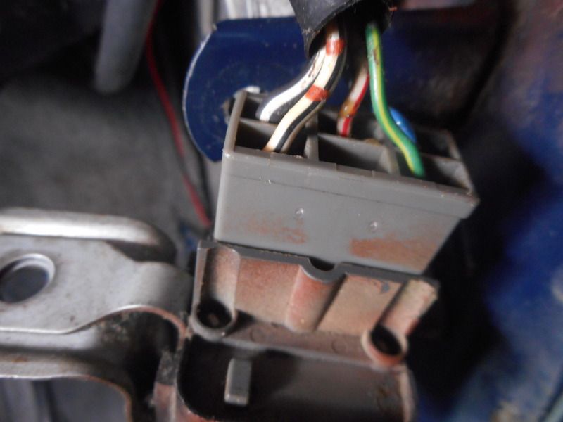
Not sure what pictures you wanted to see. I posted two pictures here. The 1st one is of the COR relay plugged into the harness. The 2nd picture is of the COR relay harness. I did not see any ground point areas in this location. This area is at the right side kick panel area. After you remove the panel, this is what you see. The COR relay was bolted to that hole to the left and up a little. No signs of any kind of rust. The body is in good shape.


chevy55
Discussion starter
104 posts
·
Joined 2018
Ok, I disconnected the wire connector to the COR relay. I then did a continuity check on the blue wire from the COR relay wire connector to the fuel pump wire connector and it checked out ok. I did the same on the white and black wire also from the COR relay to the fuel pump wire connector. It to turned out ok. And to see if the fuel pump is good, I left the fuel pump wire connector disconnected and ran a jumper wire from the blue wire terminal on the pump side, to the COR relay wire connector at the white and red wire terminal, this is with the COR relay disconnected. I then ran another jumper wire from the white and black terminal of the fuel pump up all the way forward to the negative battery terminal. With these jumpers installed, the engine starts up on a dime. Now, if I remove these jumpers and plug the fuel pump connector back and connect the COR relay connector back, the engine won't start. With the key on, I'm not getting voltage on the blue wire from the COR relay to the fuel pump, and I'm not getting a ground signal on the white with black wire from the COR relay to the fuel pump. Could the problem be with the COR relay, or something before the COR relay? Any help is greatly appreciated. Thank you, Tommy. Continued on Page-3
chevy55
Discussion starter
104 posts
·
Joined 2018
I found this article below which states exactly how the (AFM) Air Flow Meter and the (ECU) Engine Control Unit or also know as (ECM) Engine Control Module work together. This is a little too deep for me. I hope someone out there understands this theory of operation. And can diagnose what is going on with my ignition system. You will have to read the previous postings to get a good idea of what is currently happening. Two problems are: I'm not getting voltage to the blue fuel pump wire from the COR relay location running to the fuel pump. Also, I'm not getting a ground reading from and to the same location. Hope this helps. Thank you for your support, Tommy.
Theory of Operation:
So, how exactly does the AFM work? It is basically an input sensor to the ECU (Engine Control Unit). In the schematic diagram below, you can see how the ECU and AFM are connected. Basically the ECU receives the B+ battery voltage(about 14 volts with the engine running) from the Main Relay. It passes this voltage on to the AFM via the VB terminal. The voltage at the VC terminal is used by the ECU as a refererence voltage (it should be around 12 volts) and that voltage is basically the highest voltage that it would see from the air flow part of the sensor. And it is the air flow that is sensed as a voltage on the VS terminal. As you can see in the voltage graph in the lower left corner, the VS voltage runs from around 0 volts up to around 12 volts depending on the air flowing through the AFM.
It is actually quite a simple circuit, as you just have the ECU's internal resistor (R) and the VB to VC resistance (R1) and finally the VC to E2 resistance (R2) in series between B+ and ground, so there is just a constant current flowing through those 3 resistors (I = V/(R + R1 + R2) ). And the VS terminal just pulls off some portion of the voltage across R2 to send back to the ECU.
The two final portions of the AFM are the intake air temperature sensor THA and the fuel pump contacts FC and E1. The THA circuit is just a temperature sensitive resistor in series with a fixed resistor (R) inside the ECU and the ECU "sees" the voltage across THA to ground and uses this to determine the temperature of the intake air, which affects its density. And since the density of the air affects how far the AFM sensing vane is pushed open for a given volume of air passing through it, the ECU needs to know both the temperature and the volume or air in order to estimate the mass (or weight) of air (or oxygen) coming into the engine. And finally, the FC and E1 contacts, which you will note do not connect to the ECU, are used to keep the Circuit Opening Relay energized which in turn keeps the fuel pump running as long as air is passing through the AFM. So this is a safety feature or sorts. If the engine stops, say in a traffic accident, the fuel pump is shut off to minimize the chance of high pressure fuel leaks and fire. Also, if you were to run out of gas, the engine would of course stop and thus the fuel pump would also be stopped and this can help prevent damage to the pump as it is both cooled and lubricated by the fuel it is pumping. If the pump were to keep running, it would likely be damaged in short order. Note, the schematic diagram below is somewhat generic in that the exact connections to the ECU may not match any given wiring diagram. So you should go by the FSM wiring diagram for your specific vehicle for exact connections.
chevy55
Discussion starter
104 posts
·
Joined 2018
Ok, I installed all wire connectors back to where they belong. Then I placed a jumper from +B to FP terminals of the Data Link Connector shown below. The engine started up and runs. I ran it for about 3 minutes. I kept feeling how hot the EFI relay was getting. At about 3 minutes it got real hot to a touch. So, I turned off the ignition switch. So, I am back to where I was before the engine stopped starting and running. Only now, the engine starts with the bypass wire installed and runs. So now, I have to find out why the EFI relay is getting hot like it is. I'm taking a chance and I'm purchasing a used COR relay from Ebay. I'm hoping that this is the cause for all my problems. We shall see. Any comments? Thank you, Tommy.


15,316 posts
·
Joined 2006
You should be able to measure the amount of amps the fuel pump is pulling. BTW, have you inspected yer fuel filter to make sure it's not restricted or clogged up? I had an issue with my 1996 T-100 where the EFI fuse kept blowing and I discovered that the fuel pump was pulling a lot of amps. I eventually pulled the fuel filter and found out it was really restricted so that the fuel pump was fighting a lot of pressure. I did a reverse blow on it and a lot of crud came out of my filter. I ended up replacing it with an aftermarket one from the box auto parts store and it's been working just fine since. Just something to think about.
chevy55
Discussion starter
104 posts
·
Joined 2018
Both fuel filters were replaced. The inner and outer. With the jumper installed at the Data Link Connector, the engine starts up on a dime and runs smooth. So, when I bypass the relays, the engine starts up and runs fine except for the EFI relay heating up. With that said, I will recheck the EFI relay contacts. I'm thinking bad connections. I'll check them tomorrow. I will also see if I can check how many amps the fuel pump is drawing. Thank you for your support, Tommy.
601 posts
·
Joined 2012
That EFI relay getting hot has been consistent. That seems to tell us the problem (high resistance causing the heat) is right there. I went back through your thread but have not seen that you have replace or tried to swap out that relay. Can you do that?
If not, perhaps can you pull the relay out of it's socket and identify and jump across the connections in the socket to provide the 12volt path to the fuel pump (FP) - trying to do what the relay's internal contacts switch does when it completes the circuit to the FP. If this can be done and there is no heating of the jumper wire it could tell you that resistance (source of that heat) is within the EFI relay. This sounds too simple though so you've probably already tried it, or have replaced that relay?
With all of that said, Toyota relays from this era are general very, very reliable.
15,316 posts
·
Joined 2006
Based on the EWD that you provided, locate and check ground point A to see how good that ground contact is. With a poor ground connection, the relay (coil side) will pull more amps than normal and can cause the relay coil to heat up. Post piccies where it's located and the current (no pun intended) condition.
chevy55
Discussion starter
104 posts
·
Joined 2018
Yes, replacing the EFI relay with a new one was one of the first things we tried. The 12 volt path to the fuel pump starts from the 15 amp EFI fuse through the black/green wire hot at all times. When the Main EFI relay contact closes the voltage runs from the black/green wire through the relay to the white/red wire to the COR relay. When the COR relay contact closes the voltage runs through the blue wire to the fuel pump. So, it appears to me that the problem is not with the voltage, it's getting that voltage running through these relays is the problem. The side that kicks these relays to close the contacts so that the voltage is allowed to travel seems to be the problem. That's what I think anyway. The main fuse box in the engine compartment is old and the contact points in this fuse box are bad all over the place. The first place I had to troubleshoot was the 12 voltage from the black/yellow wire from the ignition switch to the 7.5 amp fuse in the fuse box. There is 12 volts from the ignition switch however when that wire gets to the 7.5 amp fuse, there is no voltage to be found. So, I had to run a temporary jumper from the ignition switch to the 7.5 amp fuse. Without this jumper installed the main EFI relay contact would not close, therefor there would no voltage running through the EFI relay to the COR relay. I still have that temporary jumper installed. The real big problem is that the wiring diagrams that I'm able to find on the internet do not match up with what this truck has. I also have a Chilton's repair manual that I use and it too does not match up with what the truck has. The color with the wires and where they suppose to be running no not match up. This makes things very difficult to diagnose. For example: The black/yellow wire from the ignition switch is suppose to run directly to the 7.5 amp fuse in the fuse box. Instead there is a yellow/blue wire on one side of the 7.5 amp fuse, and a solid yellow wire on the other side. These wires were not tampered with either. It is clearly factory installed wiring. Also, a lot of the terminals in the fuse box are defective. They may have voltage coming in from under the fuse box to a terminal at the base of the fuse box. Then when I check voltage at the top of the fuse box at that same terminal, there's nothing, no voltage. I found this condition in more than one terminal in the fuse box. So, right now, I have two temporary jumpers installed to get voltage running up to the COR relay. The first jumper is like I mentioned earlier, from the ignition switch to the 7.5 amp fuse. Then from the 7.5 amp fuse to the EFI relay. This is the source that closes the Main EFI relay which allows voltage to run to the COR relay. Can't help but think that the problems are due to bad contacts in the fuse box and a bad ground somewhere. I will be rechecking the ground that supports the Main EFI relay today. Thank you for your support. Keep them thoughts coming. I appreciate it.
-
?
-
?
-
?
-
?
-
?
-
?
-
?
-
?
-
?
-
?
-
?
-
?
-
?
-
?
-
?
-
?
-
?
-
?
-
?
-
?
- posts
- 6.4M
- members
- 659K
- Since
- 2001
ToyotaNation Forum is a community dedicated to all Toyota models. Come discuss the Camry, Tacoma, Highlander, 4Runner, Rav4, Corolla, Rav4 Prime and more!

Top Contributors this Month
View All
sdspeed
169 Replies
98LE2.2LCamryUS
165 Replies
ForaFrank
150 Replies